Symmetrical Components and Symmetrical and Unsymmetrical Faults · Power System Analysis · GATE EE
Marks 1
The initial three-phase voltage phasors ( $\vec{V}_A, \vec{V}_B$, and $\vec{V}_C$ ) at a bus of a power network are as shown in Case-1. Due to a disturbance, the bus voltage phasors changed in phase by a small angle $\Delta \theta$, and the magnitudes remained the same as depicted in Case- 2 .
 Which one of the following statements is correct about the zero sequence components?
The bus impedance matrix of a 3-bus system (in pu) is
$$ Z_{\text {bus }}=\left[\begin{array}{lll} j 0.059 & j 0.061 & j 0.038 \\ j 0.061 & j 0.093 & j 0.066 \\ j 0.038 & j 0.066 & j 0.110 \end{array}\right] $$
A symmetrical fault (through a fault impedance of $j 0.007$ p.u.) occurs at bus 2 . Neglecting pre-fault loading conditions, the voltage at bus 1 , during the fault is __________ p.u. (round off to three decimal places).
The valid positive, negative and zero sequence impedances (in p.u.), respectively, for a 220 kV, fully transported three-phase transmission line, from the given choices are
If the positive sequence impedance is (1 + 𝑗 10) $$\Omega $$, and the zero sequence is (4 + 𝑗 31) $$\Omega $$, then the imaginary part of Zm (in $$\Omega $$) is ______(up to 2 decimal places).
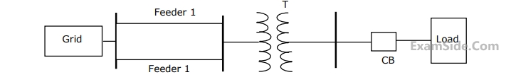
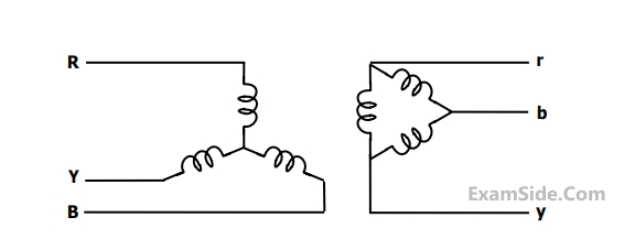
The transformers T1 and T2 are connected as
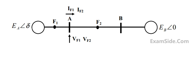
If the fault takes place at location $${F_1}$$, then the voltage and the current at bus A are $${V_F1}$$ and $${{\rm I}_{F1}}$$ respectively. If the fault takes place at location $${F_2}$$, then the voltage and the current at bus A are $${V_{F2}}$$ and $${{\rm I}_{F2}}$$ respectively.
The correct statement about voltages and currents during faults at $${F_1}$$ and $${F_2}$$ is
$${{\rm I}_{positive}} = j1.5\,pu,\,\,{{\rm I}_{negative}} = - j0.5\,\,pu,$$
$${{\rm I}_{zero}} = - j1\,\,pu.$$ The typeof fault in the system is

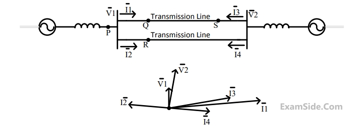
Voltage drop across the transmission line is given by the following equation:
$$$\left[ {\matrix{
{\Delta {V_a}} \cr
{\Delta {V_b}} \cr
{\Delta {V_c}} \cr
} } \right] = \left[ {\matrix{
{{Z_s}} & {{Z_m}} & {{Z_m}} \cr
{{Z_m}} & {{Z_s}} & {{Z_m}} \cr
{{Z_m}} & {{Z_m}} & {{Z_s}} \cr
} } \right]\left[ {\matrix{
{{i_a}} \cr
{{i_b}} \cr
{{i_c}} \cr
} } \right]$$$
Shunt capacitance of the line can be neglect. If the line has positive sequence impedance of $$15\,\,\Omega $$ and zero sequence in impedance of $$48\,\,\Omega ,$$ then the values of $${{Z_s}}$$ and $${{Z_m}}$$ will be
Marks 2
In the circuit shown, the phase currents are
$$ \begin{aligned} & I_A=572.812+j 50.115 \mathrm{~A} \\ & I_B=-254.525-j 459.175 \mathrm{~A} \\ & I_C=-207.083+j 444.091 \mathrm{~A} \end{aligned} $$

Given that the CTs are ideal with no saturation, and the turns ratio of the Main CT is $300: 5$ and that of the Auxiliary Transformer $(Y n \Delta)$ is $2: 1$ on every phase, the value of $I_{A R}$, rounded off to three decimal places, is
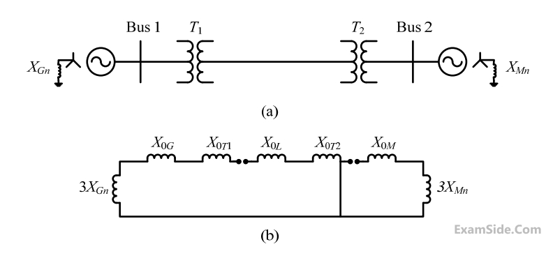
The two-bus power system shown in figure (i) has one alternator supplying a synchronous motor load through a Y-$$\Delta$$ transformer. The positive, negative and zero-sequence diagrams of the system are shown in figures (ii), (iii) and (iv), respectively. All reactances in the sequence diagrams are in p.u. For a bolted line-to-line fault (fault impedance = zero) between phases 'b' and 'c' at bus 1, neglecting all pre-fault currents, the magnitude of the fault current (from phase 'b' to 'c') in p.u. is ____________ (Round off to 2 decimal places).


Suppose $I_A, I_B$ and $I_C$ are a set of unbalanced current phasors in a three-phase system. The phase-B zero-sequence current $I_{B 0}=0.1 \angle 0^0$ p.u. If phase-A current $I_A=1.1 \angle 0^0$ p.u and phase- $C$ current $I_C=\left(1 \angle 120^0+0.1\right)$ p.u., then $I_B$ in p.u is
Nominal system frequency $$= 50$$ $$Hz.$$ The reference voltage for phase $$'a'$$ is defined as $$\,\,V\left( t \right) = {V_m}\,\cos \left( {\omega t} \right).\,\,\,$$ A symmetrical $$3\phi $$ fault occurs at centre of the line, i.e., at point $$'F'$$ at time 'to' the $$+ve$$ sequence impedance from source $${S_1}$$ to point $$'F'$$ equals $$(0.004 + j \,\,0.04)$$ $$p.u.$$ The wave form corresponding to phase $$'a'$$ fault current from bus $$X$$ reveals that decaying $$d.c.$$ offset current is $$-ve$$ and in magnitude at its maximum initial value. Assume that the negative sequence are equal to $$+ve$$ sequence impedances and the zero sequence $$(Z)$$ are $$3$$ times $$+ve$$ sequence $$(Z).$$
The instant $$\,\left( {{t_0}} \right)\,\,$$ of the fault will be
Nominal system frequency $$= 50$$ $$Hz.$$ The reference voltage for phase $$'a'$$ is defined as $$\,\,V\left( t \right) = {V_m}\,\cos \left( {\omega t} \right).\,\,\,$$ A symmetrical $$3\phi $$ fault occurs at centre of the line, i.e., at point $$'F'$$ at time 'to' the $$+ve$$ sequence impedance from source $${S_1}$$ to point $$'F'$$ equals $$(0.004 + j \,\,0.04)$$ $$p.u.$$ The wave form corresponding to phase $$'a'$$ fault current from bus $$X$$ reveals that decaying $$d.c.$$ offset current is $$-ve$$ and in magnitude at its maximum initial value. Assume that the negative sequence are equal to $$+ve$$ sequence impedances and the zero sequence $$(Z)$$ are $$3$$ times $$+ve$$ sequence $$(Z).$$
Instead of the three phase fault, if a single line to ground fault occurs on phase $$' a '$$ at point $$' F '$$ with zero fault impedance, then the $$rms$$ of the ac component of fault current $$\left( {{{\rm I}_x}} \right)$$ for phase $$'a'$$ will be
Nominal system frequency $$= 50$$ $$Hz.$$ The reference voltage for phase $$'a'$$ is defined as $$\,\,V\left( t \right) = {V_m}\,\cos \left( {\omega t} \right).\,\,\,$$ A symmetrical $$3\phi $$ fault occurs at centre of the line, i.e., at point $$'F'$$ at time 'to' the $$+ve$$ sequence impedance from source $${S_1}$$ to point $$'F'$$ equals $$(0.004 + j \,\,0.04)$$ $$p.u.$$ The wave form corresponding to phase $$'a'$$ fault current from bus $$X$$ reveals that decaying $$d.c.$$ offset current is $$-ve$$ and in magnitude at its maximum initial value. Assume that the negative sequence are equal to $$+ve$$ sequence impedances and the zero sequence $$(Z)$$ are $$3$$ times $$+ve$$ sequence $$(Z).$$
The $$rms$$ value of the ac component of fault current $$\,\left( {{{\rm I}_x}} \right)$$ will be
$$\left[ {\matrix{ {{f_a}} \cr {{f_b}} \cr {{f_c}} \cr } } \right] = k\left[ {\matrix{ 1 & 1 & 1 \cr {{\alpha ^2}} & \alpha & 1 \cr \alpha & {{\alpha ^2}} & 1 \cr } } \right]\left[ {\matrix{ {{f_p}} \cr {{f_n}} \cr {{f_o}} \cr } } \right]$$ where $$\,\alpha = {e^{j{{2\pi } \over 3}}}\,\,$$ and $$k$$ is a constant
Now, if it is given that:
$$\left[ {\matrix{ {{V_p}} \cr {{V_n}} \cr {{V_o}} \cr } } \right] = k\left[ {\matrix{ {0.5} & 0 & 0 \cr 0 & {0.5} & 0 \cr 0 & 0 & {2.0} \cr } } \right]\left[ {\matrix{ {{i_p}} \cr {{I_n}} \cr {{i_o}} \cr } } \right]\,\,$$ and $$\left[ {\matrix{ {{V_a}} \cr {{V_b}} \cr {{V_c}} \cr } } \right] = z\left[ {\matrix{ {{i_a}} \cr {{I_b}} \cr {{i_c}} \cr } } \right]\,\,$$ then,
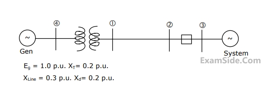
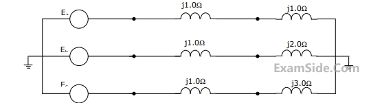
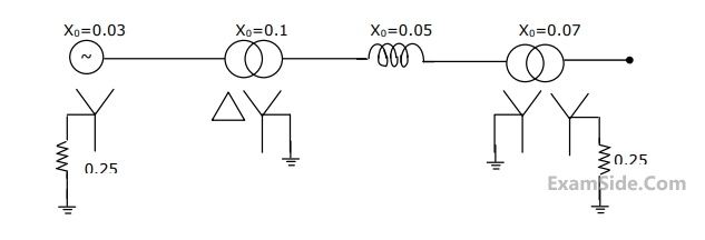
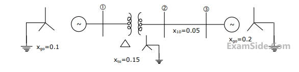
The zero sequence driving point reactance at the bus is
The positive sequence driving point reactance at the bus is
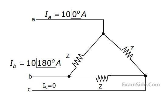
$${E_a} = 10\angle {0^ \circ }V,\,\,\,{E_b} = 10\angle - {90^ \circ }V,\,\,{E_c} = 10\angle {120^ \circ }\,\,V.\,\,\,\,$$ The positive sequence component of the load current is
$$1.0$$ p.u. and $${Z_1} = {Z_2} = j0.1\,\,$$ p.u.,
$$\,{Z_0} = j0.05\,\,\,\,\,$$ p.u., for the alternator, then the required inductive reacttance for neutral grounding is
Marks 5
(a) Draw the positive, negative, and zero sequence networks for the fault given.
(b) Draw the interconnection of the sequence networks for the fault analysis.
(c) Determine the fault current.