Parameters and Performance of Transmission Lines · Power System Analysis · GATE EE

Start Practice

Marks 1

1

A 50 Hz, 275 kV line of length 400 km has the following parameters:

Resistance, R = 0.035 $$\Omega$$/km;

Inductance, L = 1 mH/km;

Capacitance, C = 0.01 $$\mu$$F/km;

The line is represented by the nominal-$$\pi$$ model. With the magnitudes of the sending end and the receiving end voltages of the line (denoted by $$V_S$$ and $$V_R$$, respectively) maintained at 275 kV, the phase angle difference ($$\theta$$) between $$V_S$$ and $$V_R$$ required for maximum possible active power to be delivered to the receiving end, in degree is ___________ (Round off to 2 decimal places).

GATE EE 2023
2

The geometric mean radius of a conductor, having four equal strands with each strand of radius r, as shown in the figure below, is

GATE EE 2022 Power System Analysis - Parameters and Performance of Transmission Lines Question 2 English

GATE EE 2022
3
In the figure, the voltages are

$${v_1}\left( t \right) = 100\cos \left( {\omega t} \right)$$

$${v_2}\left( t \right) = 100\cos \left( {\omega t + {\pi \over {18}}} \right)$$

and $${v_3}\left( t \right) = 100\cos \left( {\omega t + {\pi \over {36}}} \right)$$.

The circuit is in sinusoidal steady state, and R << $${\omega L}$$. P1, P2 and P3 are the average power outputs. Which one of the following statements is true? GATE EE 2018 Power System Analysis - Parameters and Performance of Transmission Lines Question 4 English
GATE EE 2018
4
The normal - $$\pi $$ circuit of a transmission line is shown in the figure. GATE EE 2017 Set 2 Power System Analysis - Parameters and Performance of Transmission Lines Question 61 English

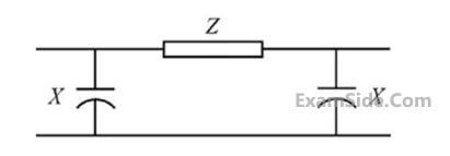
Impedance $$Z = 100\angle {80^ \circ }$$ and reactance $$\,X = 3300\Omega .$$ The magnitude of the characteristic impedance of the transmission line, in $$\Omega ,$$ is ________. (Give the answer up to one decimal place.)

GATE EE 2017 Set 2
5
A source is supplying a load through a 2-phase, 3-wire transmission system as shown in figure below. The instantaneous voltage and current in phase-a are $$v_{an}=220\sin\left(100\mathrm{πt}\right)\;V$$ and $$i_a=10\sin\left(100\mathrm{πt}\right)\;A$$, respectively. Similarly for phase-b the instantaneous voltage and current are $$v_{bn}=220\cos\left(100\mathrm{πt}\right)\;V$$ and $$i_b=10\cos\left(100\mathrm{πt}\right)\;A$$, respectively. GATE EE 2017 Set 1 Power System Analysis - Parameters and Performance of Transmission Lines Question 96 English The total instantaneous power flowing form the source to the load is
GATE EE 2017 Set 1
6
A single phase induction motor draws $$12MW$$ power at $$0.6$$ lagging power. A capacitor is connected in parallel to the motor to improve the power factor of the combination of motor and capacitor to $$0.8$$ lagging. Assuming that the real and reactive power drawn by the motor remains same as before, the reactive power delivered by the capacitor in MVAR is _______ .
GATE EE 2014 Set 2
7
In a long transmission line with $$r, l, g$$ and $$𝑐$$ are the resistance, inductance, shunt conductance and capacitance per unit length respectively, the condition for distortionless transmission is
GATE EE 2014 Set 3
8
The undesirable property of an electrical insulating material is
GATE EE 2014 Set 1
9
A single load is supplied by a single voltage source. If the current flowing from the load to the source is $$10\angle - {150^0}$$ A and if the voltage at the load terminals is $$100\angle {60^0}$$ $$V,$$ then the
GATE EE 2013
10
A nuclear power station of $$500$$ $$MW$$ capacity is located at $$300$$ km away from a load center. Select the most suitable power evacuation transmission configuration among the following options.
GATE EE 2011
11
For enhancing the power transmission in along $$EHV$$ transmission line, the most preferred is to connect a
GATE EE 2011
12
Consider a step voltage wave of magnitude $$1$$ pu travelling along a loss less transmission line that terminates in a reactor. The voltage magnitude across the reactor at the instant the travelling wave reaches the reactor is GATE EE 2010 Power System Analysis - Parameters and Performance of Transmission Lines Question 69 English
GATE EE 2010
13
Consider two buses connected by an impedance of $$\left( {0 + j5} \right)\Omega .$$ The bus $$1$$ voltage is $$100$$$$\angle {30^ \circ }\,\,\,V,$$ and bus $$2$$ voltage is $$100\angle {0^ \circ }\,\,\,V,$$ The real and reactive power supplied by bus $$1,$$ respectively, are
GATE EE 2010
14
For a fixed value of complex power flow in a transmission line having a sending end voltage $$V$$, the real power loss will be proportional to
GATE EE 2009
15
An extra high voltage transmission line of length $$300$$ km can be approximate by a lossless line having propagation constant $$\beta = 0.00127$$ radians per km. then the percentage ratio of line length to wavelength will be given by
GATE EE 2008
16
Consider a bundled conductor of an overhead line consisting of three identical sub-conductors placed at the corners of an equilateral triangle as shown in figure. If we neglect the charges on the other phase conductors and ground, and assume that spacing between sub-conductors is much larger than their radius, the maximum electric field intensity is experienced at GATE EE 2007 Power System Analysis - Parameters and Performance of Transmission Lines Question 5 English
GATE EE 2007
17
Consider the transformer connections in a part of a power system shown in the figure. The nature of transformer connections and phase shifts are indicated for all but one transformer. Which of the following connections, and the corresponding phase shift $$\theta ,$$ should be used for the transformer between $$A$$ and $$B$$? GATE EE 2007 Power System Analysis - Parameters and Performance of Transmission Lines Question 6 English
GATE EE 2007
18
The concept of an electricity short, medium and long line is primarily based on the
GATE EE 2006
19
A $$400$$ V, $$50$$ Hz, three phase balanced source supplies power to a star connected load whose rating is $$12\sqrt 3 $$ kVA, $$0.8$$ pf(lag). The rating (in kVAR) of the delta connected (capacitive) reactive power bank neccessary to bring the pf to unity is
GATE EE 2006
20
The insulation strength of an EHV transmission line is mainly governed by
GATE EE 2005
21
The phase sequence of the $$3$$-phase system shown in figure is GATE EE 2004 Power System Analysis - Parameters and Performance of Transmission Lines Question 75 English
GATE EE 2004
22
The rated voltage of a $$3$$-phase power system is given as
GATE EE 2004
23
Total instantaneous power supplied by a $$3$$-phase ac supply to a balanced $$R$$-$$L$$ load is
GATE EE 2004
24
Bundled conductors are mainly used in high voltage overhead transmission lines to
GATE EE 2003
25
A $$3$$-phase, $$11$$-$$kV$$ generator feeds power to a constant power unity power factor load of $$100$$ $$MW$$ through a $$3$$-phase transmission line. The line-to-line voltage at the terminals of the machine is maintained constant at $$11$$ $$kV$$. The per unit positive sequence impedance of the line based on $$100$$ $$MVA$$ and $$11$$ $$kV$$ is $$j$$ $$0.2$$. The line to line voltage at the load terminals is measured to be less than $$11$$ $$kV$$. The total reactive power to be injected at the terminals of the load to increase the line-to-line voltage at the load terminals to $$11$$ $$kV$$ is
GATE EE 2003
26
A long wire composed of a smooth round conductor runs above and parallel to the ground (assumed to be a large conducting plane). A high voltage exists between the conductor and the ground. The maximum electric stress occurs at
GATE EE 2002
27
Consider a long, two-wire line composed of solid round conductors. The radius of both conductors is $$0.25$$ cm and the distance between their centers is $$1$$m. If this distance is doubled, then the inductance per unit length.
GATE EE 2002
28
A lossless radial transmission line with surge impedance loading
GATE EE 2001
29
The load carrying capability of a long AC transmission line is
GATE EE 1999
30
An overhead line having a surge impedance of $$400$$$$\Omega $$ is connected in series with an underground cable having a surge impedance of $$100$$$$\Omega $$. If a surge of $$50$$ $$kV$$ travels from the line end towards the cable junctions, the value of the transmitted voltage wave at the junction is
GATE EE 1999
31
Corona losses are minimized when
GATE EE 1999
32
The reflection coefficient for the transmission line shown in figure at $$P$$ is GATE EE 1998 Power System Analysis - Parameters and Performance of Transmission Lines Question 87 English
GATE EE 1998
33
Series capacitive compensation in $$EHV$$ transmission lines is used to
GATE EE 1998
34
For a $$500$$ Hz frequency excitation, a $$50$$ km short power line will be modeled as
GATE EE 1996
35
The surge impedance of a $$400$$ km long overhead transmission line is $$400$$ $$\Omega $$. For a $$200$$ km length of the same line, the surge impedance will be
GATE EE 1995
36
The insulation resistance of a cable of length $$10$$ km is $$1$$ $$M\Omega $$. For a length of $$100$$ km of the same cable, the insulation resistance will be
GATE EE 1995
37
The insulation level of a $$400$$ kV, EHV overhead transmission line is decided on the basis of
GATE EE 1995
38
In a $$400$$ kV network, $$360$$ kV is recorded at a $$400$$ kV bus. The reactive power absorbed by a shunt reactor rated for $$50$$ MVAR, $$400$$ kV connected at the bus is
GATE EE 1994
39
A three phase overhead transmission line has its conductors horizontally spaced with spacing between adjacent conductors equal to 'd'. If now the conductors of the line are rearranged to form an equilateral triangle of sides equal to 'd' then
GATE EE 1993
40
The inductance of a power transmission line increases with
GATE EE 1992
41
The selection of size of conductors for a distributor in a distribution system is governed by
GATE EE 1992

Marks 2

1
Consider the two bus power system network with given loads as shown in the figure. All the values shown in the figure are in per unit. The reactive power supplied by generator G1 and G2 are QG1 and QG2 respectively. The per unit values of QG1, QG2, and line reactive power loss (Qloss) respectively are GATE EE 2018 Power System Analysis - Parameters and Performance of Transmission Lines Question 3 English
GATE EE 2018
2
A 3-phase 50 Hz generator supplies power of 3 MW at 17.32 kV to a balanced 3-phase inductive load through an overhead line. The per phase line resistance and reactance are 0.25 $$\Omega $$ and 3.925 $$\Omega $$ respectively. If the voltage at the generator terminal is 17.87 kV, the power factor of the load is ________.
GATE EE 2017 Set 2
3
Consider an overhead transmission line with $$3$$-phase, $$50$$ $$Hz$$ balanced system with conductors located at the vertices of an equilateral triangle of length $$\,{D_{ab}} = {D_{bc}} = {D_{ca}} = 1\,\,\,$$ m as shown in figure below. The resistance of the conductors are neglected. The geometric mean radius (GMR) of each conductor is $$0.01$$ $$m$$. Neglect the effect of ground, the magnitude of positive sequence reactance in $$\,\Omega $$/$$km$$ (rounded off to three decimal places) is ________________. GATE EE 2017 Set 2 Power System Analysis - Parameters and Performance of Transmission Lines Question 17 English
GATE EE 2017 Set 2
4
A load is supplied by a $$230$$ $$V,$$ $$50$$ $$Hz$$ source. The active power $$P$$ and the reactive power $$Q$$ consumed by the load are such that $$1$$ $$kW$$ $$ \le P \le 2\,kW\,\,$$ and $$\,1\,\,kVAR \le 2\,\,kVAR.\,\,$$ A capacitor connected across the load for power factor correction generates $$1$$ $$kVAR$$ reactive power. The worst case power factor after power factor correction is
GATE EE 2017 Set 1
5
A three-phase cable is supplying $$800$$ kW and $$600$$ kVAr to an inductive load. It is intended to supply an additional resistive load of $$100$$ kW through the same cable without increasing the heat dissipation in the cable, by providing a three-phase bank of capacitors connected in star across the load. Given the line voltage is $$3.3$$ kV, $$50$$ Hz, the capacitance per phase of the bank expressed in microfarads, is ________.
GATE EE 2016 Set 1
6
A single-phase transmission line has two conductors each of 10 mm radius. These are fixed at a center-to-center distance of 1 m in a horizontal plane. This is now converted to a three-phase transmission line by introducing a third conductor of the same radius. This conductor is fixed at an equal distance D from the two single-phase conductors. The three-phase line is fully transposed. The positive sequence inductance per phase of the three phase system is to be 5% more than that of the inductance per conductor of the single phase system. The distance D, in meters, is ________.
GATE EE 2016 Set 1
7
A composite conductor consists of three conductors of radius $$R$$ each. The conductors are arranged as shown below. The geometric mean radius (GMR) (in cm) of the composite conductor is kR. The value of k is ______. GATE EE 2015 Set 2 Power System Analysis - Parameters and Performance of Transmission Lines Question 22 English
GATE EE 2015 Set 2
8
The horizontally placed conductors of a single phase line operating at $$50$$ $$Hz$$ are having outside diameter of $$1.6$$ cm, and the spacing between centers of the conductors is $$6$$ m. The permittivity of free space is $$8.854 \times {10^{ - 12}}\,\,F/m.$$ The capacitance to ground per kilometer of each line is
GATE EE 2014 Set 2
9
The complex power consumed by a constant-voltage load is given by $$\left( {{P_1} + {J_{q1}}} \right).\,\,$$ Where, $$\,1\,\,kW \le \,\,{P_1} \le \,\,\,1.5\,\,kW\,\,\,$$ and $$\,\,0.5\,KVAR \le \,\,\,{Q_1} \le 1kVAR.\,\,\,$$ A compensating shunt capacitor is chosen such that $$\,\left| Q \right| \le 0.25\,\,KVAR,\,\,$$ where $$Q$$ is the net reactive power consumed by the capacitor-load combination. The reactive power (in kVAR) supplied by the capacitor is ____________.
GATE EE 2014 Set 3
10
For a $$400$$ $$km$$ long transmission line, the series impedance is $$(0.0 + j0.5)$$ $$\Omega /km$$ and the shunt admittance is $$(0.0 + j5.0)$$ $$\mu \,mho/km.$$ The magnitude of the series impedance (in $$\Omega $$) of the equivalent $$\pi $$ circuit of the transmission line is __________.
GATE EE 2014 Set 3
11
A two bus power system shown in figure supplies load of $$1.0+j0.5$$ $$p.u$$ GATE EE 2014 Set 1 Power System Analysis - Parameters and Performance of Transmission Lines Question 26 English

The value of $${V_1}$$ in $$p.u$$ and $${\delta _2}$$ respectively are

GATE EE 2014 Set 1
12
A distribution feeder of $$1$$ $$km$$ length having resistance, but negligible reactance, is fed from both the ends by $$400$$ $$V,$$ $$50$$ $$Hz$$ balanced sources. Both voltage sources $${S_1}$$ and $${S_2}$$ are in phase. The feeder supplies concentrated loads of unity power factor as shown in the figure. GATE EE 2014 Set 1 Power System Analysis - Parameters and Performance of Transmission Lines Question 27 English

The contributions of $${S_1}$$ and $${S_2}$$ in $$100$$ $$A$$ current supplied at location $$P$$ respectively, are

GATE EE 2014 Set 1
13
For the system shown below, SD1 and SD2 are complex power demands at bus $$1$$ and bus $$2$$ respectively. If $$\left| {{V_2}} \right| = 1$$ pu, the VAR rating of the capacitor (QG2) connected at bus $$2$$ is GATE EE 2012 Power System Analysis - Parameters and Performance of Transmission Lines Question 28 English
GATE EE 2012
14
A lossy capacitor $${C_x}$$, rated for operation at $$5$$ $$kV,$$ $$50$$ $$Hz$$ is represented by an equivalent circuit with an ideal capacitor $${C_p}$$ in parallel with a resistor $${R_p}$$. The value $${C_p}$$ is found to be $$0.102$$ $$\mu F$$ and the value of $${R_p}$$ $$=$$ $$1.25$$ $$M\Omega .$$ Then the power loss and $$tan\delta $$ of the lossy capacitor operating at the rated voltage, respectively, are
GATE EE 2011
15
A $$50$$ $$Hz$$ synchronous generator is initially connected to a long lossless transmission line which is open circuited at the receiving end. With the field voltage held constant, the generator is disconnected from the transmission line. Which of the following may be said about the steady state terminal voltage and field current of the generator?
GATE EE 2010
16
Consider a three-phase, $$50Hz,$$ $$11$$ $$kV$$ distribution system. Each of the conductors is suspended by an insulator string having two identical porcelain insulators. The self capacitance of the insulator is $$5$$ times the shunt capacitance between the link an the ground, as shown in the figure. The voltage across the two insulators are GATE EE 2010 Power System Analysis - Parameters and Performance of Transmission Lines Question 31 English
GATE EE 2010
17
Consider a three-core, three phase, $$50$$ $$Hz$$, $$11$$ $$kV$$ cable whose conductors are denoted as $$R, Y$$ and $$B$$ in the figure. The inter-phase capacitance $$\left( {{C_1}} \right)$$ between each pair of conductors is $$0.2$$ $$\mu F$$ and the capacitance between each line conductor and the sheath is $$0.4$$ $$\mu F$$ . The per-phase charging current is GATE EE 2010 Power System Analysis - Parameters and Performance of Transmission Lines Question 32 English
GATE EE 2010
18
Match the items List-$${\rm I}$$ (To) with the items in List-$${\rm II}$$ (Use) and select the correct answer using the codes given below the lists.

List-$${\rm I}$$
$$A.$$ improve power factor
$$B.$$ reduce the current ripples
$$C.$$ increase the power flow in line
$$D$$ reduce the Ferranti effect

List-$${\rm II}$$
$$1.$$ shunt reactor
$$2.$$ shunt capacitor
$$3.$$ series capacitor
$$4.$$ series reactor

GATE EE 2009
19
A lossless transmission line having Surge Impedance Loading $$(SIL)$$ of $$2280$$ $$MW.$$ A Series capacitive compensation of $$30$$% is emplaced. Then $$SIL$$ of the compensated transmission line will be
GATE EE 2008
20
The total reactance and total susceptance of a lossless overhead $$EHV$$ line, operating at $$50$$ $$Hz,$$ are given by $$0.045$$ pu and $$1.2$$ pu respectively. If the velocity of wave propagation is $$3\,\, \times \,\,{10^5}$$ km/s, then the approximate length of line is
GATE EE 2007
21
$$230$$ $$V$$ (phase) $$50$$ Hz, three-phase, $$4$$-wire, system has a sequence $$ABC$$. A unity power-factor load of $$4$$ kW is connected between phase A and neutral $$N$$. It is desired to achieve zero neutral current through the use of a pure inductor and pure capacitor in the other two phases. The Value of inductor and capacitor is......
GATE EE 2007
22
Single line diagram of a $$4$$-bus single source distribution system is shown below. Branches $${e_1},\,\,$$ $${e_2},\,\,$$ $${e_3}\,\,$$ and $${e_4}\,\,$$ have equal impedences. The load current values indicated in the figure are in per unit. GATE EE 2007 Power System Analysis - Parameters and Performance of Transmission Lines Question 7 English

Distribution Company's policy requires radial system operation with minimum loss. This can be achieved by opening of the branch

GATE EE 2007
23
The $$A, B, C, D$$ constant of a $$220$$ $$kV$$ line are:
$$A = D = 0.94\,\angle \,10,\,\,\,B = 130\,\angle \,730,\,\,\,C = 0.001\,\angle \,900.\,\,$$ If the sending end voltage of the line for a given load delivered at nominal voltage is $$240$$ $$kV$$, the % voltage regulation of the line is
GATE EE 2006
24
At an industrial sub-station with a $$4$$ $$MW$$ load, a capacitor of $$2$$ MVAR is installed to maintain the load power factor at $$0.97$$ lagging. If the capacitor goes out of service, the load power factor becomes
GATE EE 2005
25
A $$110$$ $$kV,$$ single core coaxial, XLPE insulated power cable delivering power at $$50$$ $$Hz,$$ has a capacitance of $$125$$ $$nF/km.$$ If the dielectric loss tangent of XLPE is $$\,2\,\, \times \,\,{10^{ - 4}},$$ the dielectric power loss in this cable in $$W/km$$ is
GATE EE 2004
26
A lightning stroke discharges impulse current of $$10$$ kA (peak) on a $$400$$ kV transmission line having surge impedance of $$250\,\Omega $$. The magnitude of transient over-voltage traveling waves in either direction assuming equal distribution form the point of lightning strike will be
GATE EE 2004
27
A $$800$$ $$kV$$ transmission line is having per phase line inductance of $$1.1$$ $$mH/km$$ and per phase line capacitance of $$11.68$$ $$nF/km.$$ Ignoring the length of the line, its ideal power transfer capability in $$MW$$ is
GATE EE 2004
28
The generalized circuit constants of a $$3$$-phase, $$220$$ $$kV$$ rated voltage, medium length transmission line are $$A = D = 0.936 + j\,0.016 = 0.936\angle {0.98^ \circ }$$
$$B = 33.5 + j138 = 142.0\angle {76.4^ \circ }\,\Omega $$
$$\,C = \left( { - 5.18 + j914} \right) \times \,{10^{ - 6}}\,\Omega $$
If the load at the receiving end is $$50$$ MW at $$220$$ $$kV$$ with a power factor of 0.9 lagging, then magnitude of line to line sending end voltage should be
GATE EE 2004
29
The ABCD parameters of a $$3$$-phase overhead transmission line are $$\,A = D = 0.9\angle {0^ \circ }.\,\,B = 200\,\angle {90^ \circ }\,\,\Omega \,\,\,$$ and $$\,\,C = 0.95\, \times \,\,{10^{ - 3}}\angle {90^ \circ }\,\,S.\,\,\,\,$$ At no-load condition, a shunt inductive reactor is connected at the receiving end of the line to limit the receiving end voltage to be equal to the sending-end voltage. The ohmic value of the reactor is
GATE EE 2003
30
A dc distribution system is shown in figure with load currents as marked. The two ends of the feeder are fed by voltage sources such that $${V_P} - {V_Q} = 3V.$$ the value of the voltage $${V_P}$$ for a minimum voltage of $$220$$ $$V$$ at any point along the feeder is GATE EE 2003 Power System Analysis - Parameters and Performance of Transmission Lines Question 43 English
GATE EE 2003
31
A surge of 20 kV magnitude travels along a lossless cable towards its junction with two identical lossless overhead transmission lines. The inductance and the capacitance of the cable are 0.4 mH and 0.5 $$\mu F$$ per km. The inductance and capacitance of the overhead transmission lines are 1.5 mH and 0.015 $$\mu F$$ per km. The magnitude of the voltage at the junction due to surge is
GATE EE 2003
32
A balanced delta connected load of $$\left( {8 + j6} \right)\Omega $$ per phase is connected to a $$400$$ $$V$$, $$50$$ $$Hz$$, $$3-$$phase supply lines. If the input power factor is to be improved to $$0.9$$ by connecting a bank of star connected capacitors the required KVAR of the bank is
GATE EE 2003
33
The conductors of a $$10$$ km long, single phase, two wire line are separated by a distance of $$1.5$$ m. The diameter of each conductor is $$1$$ cm. If the conductors are of copper, the inductance of the circuit is
GATE EE 2001
34
Consider the model shown in figure of a transmission line with a series capacitor at its mid-point. The maximum voltage on the line is at the location GATE EE 2001 Power System Analysis - Parameters and Performance of Transmission Lines Question 48 English
GATE EE 2001
35
The corona loss on a particular system at 50 Hz is 1 kW/km per phase. The corona loss at 60 Hz would be
GATE EE 2000
36
A transmission line has equal voltages at the two ends, maintained constant by two sources. A third source is to be provided to maintain constant voltage (equal to end voltages) at either the midpoint of the line or at $$75$$% of the distance from the sending end. Then the maximum power transfer capabilities of the line in the original case and the other two cases respectively will be in the following ratios.
GATE EE 2000
37
A 3-phase, 11 kV, 50 Hz, 200 kW load has a power factor of 0.8 lag. A delta connected 3-phase capacitor is used to improve the power factor to unity. The capacitance power phase of the capacitor in micro-farads is
GATE EE 1999
38
A single phase AC distributor supplies two single phase loads as shown in figure. The voltage drop from A to C is GATE EE 1999 Power System Analysis - Parameters and Performance of Transmission Lines Question 51 English
GATE EE 1999
39
$$A$$ $$220$$ kV, $$20$$ km long, $$3$$-phase transmission line has the following $$A, B, C, D$$ constants. $$A=D=0.96$$$$\angle {3^0},$$ $$\,B = 55\angle {65^0}\,\,\Omega /$$ phase, $$\,C = 0.5 \times {10^{ - 4}}\angle {90^0}\,\,$$ $$S/$$phase. Its correct charging current per phase is
GATE EE 1999
40
For a single phase overhead line having solid copper conductors of diameter $$1$$ cm, spaced $$60$$ cm between centers, the inductance in $$mH/km$$ is
GATE EE 1999
41
A shunt reactor of $$100$$ MVAR is operated at $$98$$% of its rated voltage and $$96$$% of its rated frequency. The reactive power absorbed by the reactor is;
GATE EE 1998
42
A cable has the following characteristics. $$L = 0.201\,\,\mu H/m\,\,$$ and $$\,C = 196.2\,pF/m.\,$$ The velocity of wave propagation through the cable is
GATE EE 1998
43
For equilateral spacing of conductors of an untransposed $$3$$-phase line, we have
GATE EE 1996
44
The rated load of an underground cable is always _______its natural load.
GATE EE 1995
45
Consider a three-phase, $$50$$ $$Hz$$, $$11$$ $$kV$$ distribution system. Each of the conductors is suspended by an insulator string having two identical porcelain insulators. The self capacitance of the insulator is $$5$$ times shunt capacitance. The voltage drop across botton most disc is:
GATE EE 1994
46
The charging current of a $$400$$ kV transmission line is more than that of a $$220$$ kV line of the same length.
GATE EE 1994

Marks 5

1
In a transmission line each conductor is at $$20$$ $$kV$$ and is supported by a string of $$3$$ suspension insulators. The air capacitance between each cap-pin junction and tower is one-fifth of the capacitance $$C$$ of each insulation unit. A guard ring, effective only over the line-end insulator unit is fitted so that the voltages on the two units nearest the line-end are equal. GATE EE 2003 Power System Analysis - Parameters and Performance of Transmission Lines Question 8 English

(a) Calculate the voltage on the line-end unit.
(b) Calculate the value of capacitance $${C_x}$$ required.

GATE EE 2003
2
A long lossless transmission line has a unity power factor (UPF) load at the receiving end and an ac voltage source at the sending end. The parameters of the transmission line are as follows:
Characteristic impedance $${Z_c} = 400\Omega ,\,\,$$, propagation constant $$\,\beta = 1.2 \times {10^{ - 3}}\,\,rad/km,\,\,$$ and length $$\,l = 100\,km.\,\,$$ The equation relating sending and receiving end questions is $${V_s} = {V_r}\,\cosh \,\,\left( {\beta l} \right) + j\,Z{}_c\,\,\sinh \left( {\beta l} \right){{\rm I}_R}$$ Complete the maximum power that can be transferred to the UPF load at the receiving end if $$\left| {{V_s}} \right| = 230\,\,kV.\,\,$$ GATE EE 2002 Power System Analysis - Parameters and Performance of Transmission Lines Question 9 English
GATE EE 2002
3
A 132 kV transmission line AB is connected to a cable BC. The characteristic impedances of the overhead line and the cable are 400$$\Omega $$ and 80$$\Omega $$ respectively. Assume that these are purely resistive. A 250 kV switching surge travels from A to B.

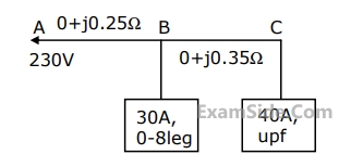
(a) Calculate the value of this voltage surge when it first reaches C.

(b) Calculate the value of the reflected component of this surge when the first reflection reaches A.

(c) Calculate the surge current in the cable BC.

GATE EE 2001
4
A $$275$$ $$kV,$$ $$3$$-phase, $$50$$ $$Hz,$$ $$400$$ $$km$$ lossless line has following parameters:
$$x=0.05$$ $$ohms/km,$$ line charging susceptance $$y=3.0$$ micro-Siemens/k.

(a) Calculate the receiving end voltage on open circuit using justifiable assumptions.

(b) What load at the receiving end will result in a flat voltage profile on the line?

(c) If the flat voltage profile is to be achieved at $$1.2$$ times the loading in (b), what will be the nature and quantum of uniformly distributed compensation required?

GATE EE 2000
5
A 66 kV, 3-phase, 50 Hz, 150 km long overhead transmission line is open circuited at the receiving end. Each conductor has a resistance of 0.25$$\Omega $$/km, an inductive reactance of 0.5$$\Omega $$/km and a capacitive admittance to neutral of 0.04 $$ \times $$ 10-4 S/km.

(a) Draw the nominal π-equivalent circuit and indicate the value of each parameter.
(b) Calculate the receiving end voltage if the sending end voltage is 66 kV.

GATE EE 1999
6
A 6.6 kV, 50 Hz single core lead sheathed cable has the following data:
Conductor diameter: 1.5 cm, length: 4 km. Internal diameter of the sheath : 3 cm
Resistivity of insulation : 1.3 $$ \times $$ 1012 $$\Omega $$-m. Relative permittivity of insulation : 3.5 Calculate

(a) the insulation resistance
(b) the capacitance and
(c) the maximum electric stress in the insulation

GATE EE 1999
7
Each conductor of a $$33$$ $$kV,$$ $$3$$ phase system is suspended by a string of three similar insulators. The ratio of shunt capacitance to mutual capacitance is $$0.1.$$ Calculate the voltage across each insulator, and the string efficiency.
GATE EE 1998
8
A factory draws $$100$$ kW at $$0.7$$ p.f. lagging from a $$3$$-phase, $$11$$ kV supply. It is desired to the p.f. to $$0.95$$ lagging using series capacitors. Calculate the rating of the capacitor required.
GATE EE 1997
9
The increase in resistance due to non-uniform distribution of current in a conducto $$r$$ is known as _______effect
GATE EE 1994
EXAM MAP
Medical
NEETAIIMS
Graduate Aptitude Test in Engineering
GATE CSEGATE ECEGATE EEGATE MEGATE CEGATE PIGATE IN
Civil Services
UPSC Civil Service
Defence
NDA
Staff Selection Commission
SSC CGL Tier I
CBSE
Class 12