1
GATE ECE 2020
MCQ (Single Correct Answer)
+1
-0.33
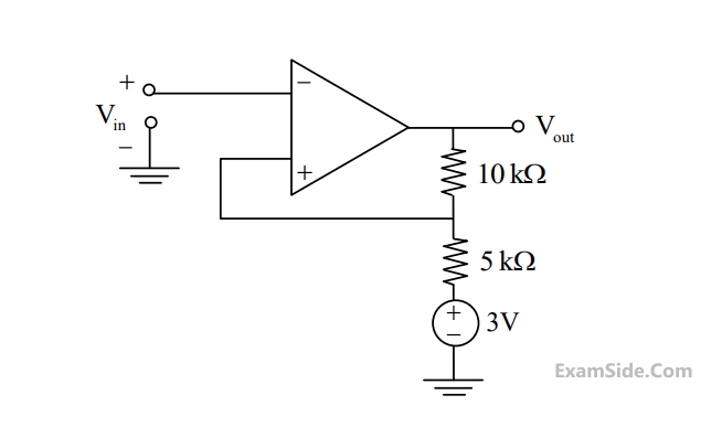
The components in the circuit shown below are ideal. If the op-amp is in positive feedback and the input voltage $V_i$ is a sine wave of amplitude 1 V , the output voltage $V_0$ is

2
GATE ECE 2020
Numerical
+1
-0
In the circuit shown below, all the components are ideal. If $V_i$ is +2 V , the current $I_0$ sourced by the OpAmp is $\_\_\_\_$ mA .

Your input ____
3
GATE ECE 2017 Set 1
MCQ (Single Correct Answer)
+1
-0.3
For the operational amplifier circuit shown, the output saturation voltages are $$ \pm \,\,15V$$. The upper and lower threshold voltages for the circuit are, respectively.
4
GATE ECE 2016 Set 1
MCQ (Single Correct Answer)
+1
-0.3
Consider the constant current source shown in the figure below. Let $$\beta $$ represent the current gain of the transistor

The load current I0 through RL is
GATE ECE Subjects
Browse all chapters by subject
General Aptitude
Network Theory
Microprocessors
Signals and Systems
Discrete Fourier Transform and Fast Fourier Transform Discrete Time Signal Fourier Series Fourier Transform Continuous Time Signal Laplace Transform Fourier Transform Representation of Continuous Time Signal Fourier Series Transmission of Signal Through Continuous Time LTI Systems Miscellaneous Sampling Continuous Time Linear Invariant System Discrete Time Linear Time Invariant Systems Discrete Time Signal Z Transform Transmission of Signal Through Discrete Time Lti Systems
Electromagnetics
Digital Circuits
Electronic Devices and VLSI
Control Systems
Communications
Engineering Mathematics