1
GATE ECE 1998
Subjective
+5
-0
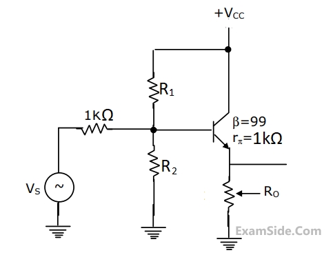
In the circuit of fig. Determine the resistance Ro seen by the output terminals, ignore the effects of R1 and R2.
2
GATE ECE 1997
Subjective
+5
-0
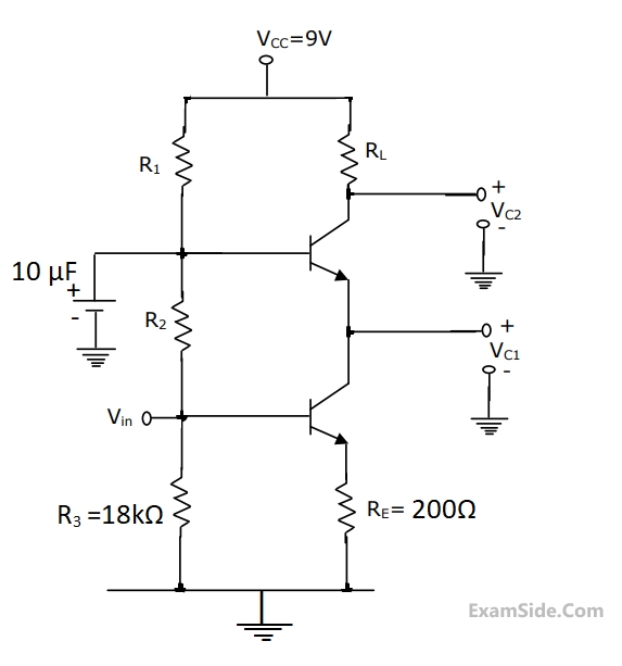
In the cascade amplifier circuit shown below, determine the values of R1, R2 and RL. Such that the quiescent current through the transistors is 1mA and the collector voltage Vc1 = 3V, and Vc2 = 6V. Tke VBE = 0.7V, Transistor $$\beta $$ to be hifgh and base currents to be negligible.
3
GATE ECE 1997
Subjective
+5
-0
The transistor in the circuit shown in the figure. is so biased (dc biasing N/W is not shown) that the dc collector current IC = 1mA. Supply is VCC = 5V.

The N/W components have following values, RC = 2$$k\Omega $$,
RS = $$1.4k\Omega $$,
RE = $$100\Omega $$.
The transistor has specifications, $$\beta \,\, = \,\,100$$
and base spreading resistance $${r_{bb\,}}^1\, = \,100\Omega $$
Evaluate input resistance Ri for two cases. At a frequency of 10 kHz
(a)CE, the bypass capacitor across RE is 25 $$\mu F$$
(b)The bypass capacitor CE is removed leaving RE unbypassed.
GATE ECE Subjects
Browse all chapters by subject
General Aptitude
Network Theory
Microprocessors
Signals and Systems
Discrete Fourier Transform and Fast Fourier Transform Discrete Time Signal Fourier Series Fourier Transform Continuous Time Signal Laplace Transform Fourier Transform Representation of Continuous Time Signal Fourier Series Transmission of Signal Through Continuous Time LTI Systems Miscellaneous Sampling Continuous Time Linear Invariant System Discrete Time Linear Time Invariant Systems Discrete Time Signal Z Transform Transmission of Signal Through Discrete Time Lti Systems
Electromagnetics
Digital Circuits
Electronic Devices and VLSI
Control Systems
Communications
Engineering Mathematics