1
GATE ECE 2007
MCQ (Single Correct Answer)
+2
-0.6
For the circuit shown in the figure, the Thevenin voltage and resistance looking
into X-Y are:

2
GATE ECE 2005
MCQ (Single Correct Answer)
+2
-0.67
For the circuit shown in figure, Thevenin’s voltage and Thevenin’s equivalent resistance at terminals a – b is

3
GATE ECE 2002
MCQ (Single Correct Answer)
+2
-0.6
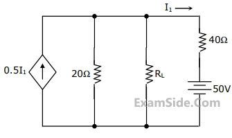
In the network of Figure, the maximum power is delivered to RL if its value is
4
GATE ECE 2001
MCQ (Single Correct Answer)
+2
-0.6
The voltage e0 in figure is

GATE ECE Subjects
Browse all chapters by subject
Control Systems
Engineering Mathematics
Analog Circuits
Network Theory
Electromagnetics
Electronic Devices and VLSI
Digital Circuits
Microprocessors
Signals and Systems
Discrete Fourier Transform and Fast Fourier Transform Discrete Time Signal Fourier Series Fourier Transform Continuous Time Signal Laplace Transform Fourier Transform Representation of Continuous Time Signal Fourier Series Transmission of Signal Through Continuous Time LTI Systems Miscellaneous Sampling Continuous Time Linear Invariant System Discrete Time Linear Time Invariant Systems Discrete Time Signal Z Transform Transmission of Signal Through Discrete Time Lti Systems
Communications
General Aptitude