A circuit with an electrical load having impedance $Z$ is connected with an AC source as shown in the diagram. The source voltage varies in time as $V(t)=300 \sin (400 t) \mathrm{V}$, where $t$ is time in s . List-I shows various options for the load. The possible currents $i(t)$ in the circuit as a function of time are given in List-II.

Choose the option that describes the correct match between the entries in List-I to those in ListII.
| List–I | List–II |
|---|---|
(P)  |
(1)  |
(Q)  |
(2)  |
(R)  |
(3)  |
(S)  |
(4)  |
(5)  |

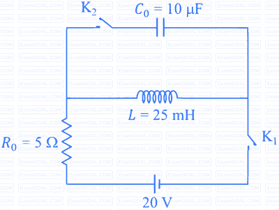
The circuit shown in the figure contains an inductor $L$, a capacitor $C_0$, a resistor $R_0$ and an ideal battery. The circuit also contains two keys $\mathrm{K}_1$ and $\mathrm{K}_2$. Initially, both the keys are open and there is no charge on the capacitor. At an instant, key $\mathrm{K}_1$ is closed and immediately after this the current in $R_0$ is found to be $I_1$. After a long time, the current attains a steady state value $I_2$. Thereafter, $\mathrm{K}_2$ is closed and simultaneously $\mathrm{K}_1$ is opened and the voltage across $C_0$ oscillates with amplitude $V_0$ and angular frequency $\omega_0$.

Match the quantities mentioned in List-I with their values in List-II and choose the correct option.
| List-I | List-II |
|---|---|
| (P) The value of $I_1$ in Ampere is | (1) $0$ |
| (Q) The value of $I_2$ in Ampere is | (2) $2$ |
| (R) The value of $\omega_0$ in kilo-radians/s is | (3) $4$ |
| (S) The value of $V_0$ in Volt is | (4) $20$ |
| (5) $200$ |

| List - I | List - II |
|---|---|
| (P) $I_0$ in $\mathrm{mA}$ | (1) 44.4 |
| (Q) The quality factor of the circuit | (2) 18 |
| (R) The bandwidth of the circuit in $\mathrm{rad}~ \mathrm{s}^{-1}$ | (3) 400 |
| (S) The peak power dissipated at resonance in Watt | (4) 2250 |
| (5) 500 |
A thermal power plant produces electric power of 600 kW at 4000 V, which is to be transported to a place 20 km away from the power plant for consumers' usage. It can be transported either directly with a cable of large current carrying capacity or by using a combination of step-up and step-down transformers at the two ends. The drawback of the direct transmission is the large energy dissipation. In the method using transformers, the dissipation is much smaller. In this method, a step-up transformer is used at the plant side so that the current is reduced to a smaller value. At the consumers' end, a step-down transformer is used to supply power to the consumers at the specified lower voltage. It is reasonable to assume that the power cable is purely resistive and the transformers are ideal with power factor unity. All the currents and voltages mentioned are rms values.
In the method using the transformers, assume that the ratio of the number of turns in the primary to that in the secondary in the step-up transformer is 1 : 10. If the power of the consumers has to be supplied at 200 V, the ratio of the number of turns in the primary to that in the secondary in the step-down transformer is