1
GATE ECE 1994
Subjective
+5
-0
Find the output voltage of the following circuit assuming ideal op-amp behavior.
2
GATE ECE 1993
Subjective
+5
-0
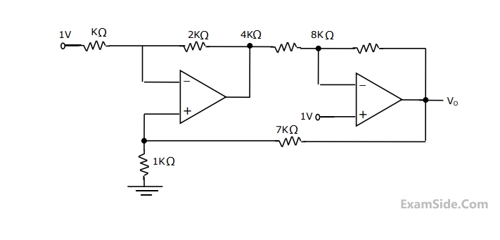
Find the output voltage, V0 in the following circuit assuming that the Op-Amps are ideal.

3
GATE ECE 1992
Subjective
+5
-0
Consider the circuit shown in Fig. The circuit uses an ideal operational amplifier. Assuming that the impedances at noodes A and B do not load the preceeding bridge circuit, calculate the output voltage Vo.

when $${R_a}\, = \,{R_b}\, = \,{R_c}\,{R_d}\,$$ ohms.
when $${R_a}\, = \,{R_b}\, = {R_c}\, = 100$$ ohms and $${R_{d\,}}\, = \,120$$ ohms.
GATE ECE Subjects
Browse all chapters by subject
Network Theory
Control Systems
Electronic Devices and VLSI
Analog Circuits
Digital Circuits
Microprocessors
Signals and Systems
Discrete Fourier Transform and Fast Fourier Transform Discrete Time Signal Fourier Series Fourier Transform Continuous Time Signal Laplace Transform Fourier Transform Representation of Continuous Time Signal Fourier Series Transmission of Signal Through Continuous Time LTI Systems Miscellaneous Sampling Continuous Time Linear Invariant System Discrete Time Linear Time Invariant Systems Discrete Time Signal Z Transform Transmission of Signal Through Discrete Time Lti Systems
Communications
Electromagnetics
General Aptitude