1
GATE ECE 2017 Set 2
Numerical
+1
-0
The output V0 of the diode circuit shown in the figure is connected to an averaging DC voltmeter. The reading on the DC voltmeter in Volts, neglecting the voltage drop across the
diode, is ____________.

Your input ____
2
GATE ECE 2017 Set 2
Numerical
+2
-0
In the circuit shown, transistors Q1 and Q2 are biased at a collector current of 2.6 mA.
Assuming that transistor current gains are sufficiently large to assume collector current equal
to emitter current and thermal voltage of 26m V, the magnitude of voltage gain Vo/Vs
in the
mid-band frequency range is _____________ (up to second decimal place).

Your input ____
3
GATE ECE 2017 Set 2
Numerical
+2
-0
In the voltage reference circuit shown in the figure, the op-amp is ideal and the transistors Q1,
Q2,….., Q32 are identical in all respects and have infinitely large values of common – emitter
current gain $$\beta $$. The collector current (IC) of the transistors is related to their base emitter voltage (VBE) by the relation IC = IS exp (VBE/VT); where Is is the saturation current. Assume that the
voltage VP shown in the figure is 0.7 V and the thermal voltage VT=26mV

The output voltage Vout (in volts) is _____.
Your input ____
4
GATE ECE 2017 Set 2
MCQ (Single Correct Answer)
+2
-0.6
Consider a binary memoryless channel characterized by the transition probability diagram shown in the figure.
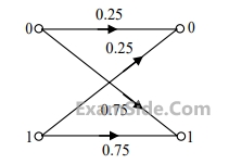 The channel is
The channel is
Paper Analysis
Total Questions
Analog Circuits 3
Communications 6
Control Systems 6
Digital Circuits 5
Electromagnetics 5
Electronic Devices and VLSI 9
Engineering Mathematics 9
Network Theory 4
Signals and Systems 6
General Aptitude 10
More Papers of GATE ECE
GATE ECE 2026 GATE ECE 2025 GATE ECE 2024 GATE ECE 2023 GATE ECE 2022 GATE ECE 2021 GATE ECE 2020 GATE ECE 2019 GATE ECE 2018 GATE ECE 2017 Set 1 GATE ECE 2017 Set 2 GATE ECE 2016 Set 1 GATE ECE 2016 Set 2 GATE ECE 2016 Set 3 GATE ECE 2015 Set 3 GATE ECE 2015 Set 1 GATE ECE 2015 Set 2 GATE ECE 2014 Set 1 GATE ECE 2014 Set 3 GATE ECE 2014 Set 4 GATE ECE 2014 Set 2 GATE ECE 2013 GATE ECE 2012 GATE ECE 2011 GATE ECE 2010 GATE ECE 2009 GATE ECE 2008 GATE ECE 2007 GATE ECE 2006 GATE ECE 2005 GATE ECE 2004 GATE ECE 2003 GATE ECE 2002 GATE ECE 2001 GATE ECE 2000 GATE ECE 1999 GATE ECE 1998 GATE ECE 1997 GATE ECE 1996 GATE ECE 1995 GATE ECE 1994 GATE ECE 1993 GATE ECE 1992 GATE ECE 1991 GATE ECE 1990 GATE ECE 1989 GATE ECE 1988 GATE ECE 1987
GATE ECE Papers
All year-wise previous year question papers
2026
2025
2024
2023
2022
2021
2020
2019
2018
2013
2012
2011
2010
2009
2008
2007
2006
2005
2004
2003
2002
2001
2000
1999
1998
1997
1996
1995
1994
1993
1992
1991
1990
1989
1988
1987