 For the circuit shown in Fig. choose state variables $$X_1,\;X_2,\;X_3$$ to be $$i_{L1}\left(t\right),\;v_{C2}\left(t\right),\;i_{L3}\left(t\right)$$
(a) Write the state equations
$$$\begin{bmatrix}{\dot X}_1\\{\dot X}_2\\{\dot X}_3\end{bmatrix}\;=\;A\;\begin{bmatrix}X_1\\X_2\\X_3\end{bmatrix}\;+\;B\left[e\left(t\right)\right]$$$(b) If e(t) = 0, t $$\geq$$ 0, $$i_{L1}\left(0\right)\;=\;0,\;v_{C2}\left(0\right)\;=\;0,\;i_{L3}\left(0\right)\;=\;1A,$$ then what would the total energy dissipated in the registors in the interval $$\left(0,\infty\right)$$ be
The voltage V in Fig. is equal to

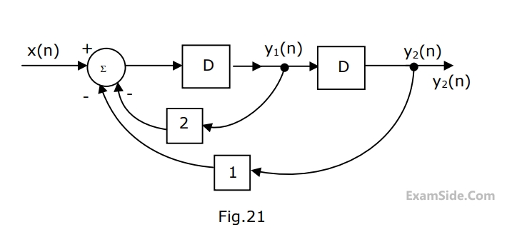
(a) Find the expression for $${y_1}\left( n \right)$$ and $${y_2}\left( n \right)$$ in terms of $$x\left( n \right).$$
(b) Find the transfer function $${y_2}\left( z \right)/X\left( z \right)$$ in the $$z$$-domain.
(c) If $$x\left( n \right) = 1$$ at $$n = 0$$ or $$x\left( n \right) = 0$$ otherwise
Find $${y_2}\left( n \right).$$
In the case of a linear time invariant system
List - 1
(1) Poles in the right half plane implies.
(2) Impulse response zero for $$t \le 0$$ implies.
List - 2
(A) Exponential decay of output
(B) System is causal
(C) No stored energy in the system
(D) System is unstable
GATE ECE Papers
All year-wise previous year question papers