1
GATE EE 2014 Set 1
MCQ (Single Correct Answer)
+1
-0.3
Three phase to ground fault takes place at locations $${F_1}$$ and $${F_2}$$ in the system shown in the figure. GATE EE 2014 Set 1 Power System Analysis - Symmetrical Components and Symmetrical and Unsymmetrical Faults Question 36 English

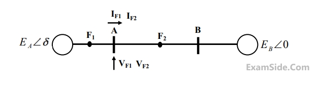
If the fault takes place at location $${F_1}$$, then the voltage and the current at bus A are $${V_F1}$$ and $${{\rm I}_{F1}}$$ respectively. If the fault takes place at location $${F_2}$$, then the voltage and the current at bus A are $${V_{F2}}$$ and $${{\rm I}_{F2}}$$ respectively.

The correct statement about voltages and currents during faults at $${F_1}$$ and $${F_2}$$ is

A
$${V_{F1}}$$ leads $${{\rm I}_{F1}}$$ and $${V_{F2}}$$ leads $${{\rm I}_{F2}}$$
B
$${V_{F1}}$$ leads $${{\rm I}_{F1}}$$ and $${V_{F2}}$$ lags $${{\rm I}_{F2}}$$
C
$${V_{F1}}$$ lags $${{\rm I}_{F1}}$$ and $${V_{F2}}$$ leads $${{\rm I}_{F2}}$$
D
$${V_{F1}}$$ $${{\rm I}_{F1}}$$ and $${V_{F2}}$$ lags $${{\rm I}_{F2}}$$
2
GATE EE 2014 Set 1
MCQ (Single Correct Answer)
+1
-0.3
A 2-bus system and corresponding zero sequence network are shown in the figure. GATE EE 2014 Set 1 Power System Analysis - Symmetrical Components and Symmetrical and Unsymmetrical Faults Question 35 English

The transformers T1 and T2 are connected as

A
GATE EE 2014 Set 1 Power System Analysis - Symmetrical Components and Symmetrical and Unsymmetrical Faults Question 35 English Option 1
B
GATE EE 2014 Set 1 Power System Analysis - Symmetrical Components and Symmetrical and Unsymmetrical Faults Question 35 English Option 2
C
GATE EE 2014 Set 1 Power System Analysis - Symmetrical Components and Symmetrical and Unsymmetrical Faults Question 35 English Option 3
D
GATE EE 2014 Set 1 Power System Analysis - Symmetrical Components and Symmetrical and Unsymmetrical Faults Question 35 English Option 4
3
GATE EE 2012
MCQ (Single Correct Answer)
+1
-0.3
The sequence components of the fault current are as follows:
$${{\rm I}_{positive}} = j1.5\,pu,\,\,{{\rm I}_{negative}} = - j0.5\,\,pu,$$
$${{\rm I}_{zero}} = - j1\,\,pu.$$ The typeof fault in the system is
A
$$LG$$
B
$$LL$$
C
$$LLG$$
D
$$LLLG$$
4
GATE EE 2008
MCQ (Single Correct Answer)
+1
-0.3
A 3-phase transmission line is shown in figure: GATE EE 2008 Power System Analysis - Symmetrical Components and Symmetrical and Unsymmetrical Faults Question 38 English

Voltage drop across the transmission line is given by the following equation: $$$\left[ {\matrix{ {\Delta {V_a}} \cr {\Delta {V_b}} \cr {\Delta {V_c}} \cr } } \right] = \left[ {\matrix{ {{Z_s}} & {{Z_m}} & {{Z_m}} \cr {{Z_m}} & {{Z_s}} & {{Z_m}} \cr {{Z_m}} & {{Z_m}} & {{Z_s}} \cr } } \right]\left[ {\matrix{ {{i_a}} \cr {{i_b}} \cr {{i_c}} \cr } } \right]$$$
Shunt capacitance of the line can be neglect. If the line has positive sequence impedance of $$15\,\,\Omega $$ and zero sequence in impedance of $$48\,\,\Omega ,$$ then the values of $${{Z_s}}$$ and $${{Z_m}}$$ will be

A
$${Z_s} = 31.5\,\Omega ;\,\,{Z_m} = 16.5\,\Omega $$
B
$${Z_s} = 26\,\Omega ;\,\,{Z_m} = 11\,\Omega $$
C
$${Z_s} = 16.5\,\Omega ;\,\,{Z_m} = 31.5\,\Omega $$
D
$${Z_s} = 11\,\Omega ;\,\,{Z_m} = 26\,\Omega $$
GATE EE Subjects
EXAM MAP
Joint Entrance Examination
JEE MainJEE AdvancedWB JEEBITSATMHT CET
Medical
NEET
Graduate Aptitude Test in Engineering
GATE CSEGATE ECEGATE EEGATE MEGATE CEGATE PIGATE IN