1
GATE EE 2008
MCQ (Single Correct Answer)
+2
-0.6
In the voltage doubler circuit shown in figure, the switch $$' S '$$ is closed at $$t=0$$. Assuming diodes $${D_1}$$ & $${D_2}$$ to be ideal, load resistance to be infinite and initial capacitor voltages to be zero, the steady state voltage across capacitors $${C_1}$$ & $${C_2}$$ will be

2
GATE EE 2006
MCQ (Single Correct Answer)
+2
-0.6
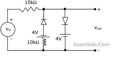
Assuming the diodes $${D_1}$$ and $${D_2}$$ of the circuit shown in the figure to be ideal ones, the transfer characteristics of the circuit will be

A

B

C

D

3
GATE EE 2004
MCQ (Single Correct Answer)
+2
-0.6
Assuming that the diodes are ideal in figure the current in the diode $${D_1}$$ is

4
GATE EE 2003
MCQ (Single Correct Answer)
+2
-0.6
A voltage signal $$\,10\,\,\sin \,\omega t\,\,$$ is applied to the circuit with ideal diodes, as shown in figure. The maximum and minimum values of the output waveform of the circuit are respectively
GATE EE Subjects
Browse all chapters by subject
Electric Circuits
Electrical Machines
Engineering Mathematics
Signals and Systems
Power Electronics
Power System Analysis
Digital Electronics
Analog Electronics
Electromagnetic Fields
Control Systems
Electrical and Electronics Measurement
General Aptitude