1
GATE EE 2004
MCQ (Single Correct Answer)
+2
-0.6
Assuming that the diodes are ideal in figure the current in the diode $${D_1}$$ is

2
GATE EE 2003
MCQ (Single Correct Answer)
+2
-0.6
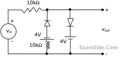
A voltage signal $$\,10\,\,\sin \,\omega t\,\,$$ is applied to the circuit with ideal diodes, as shown in figure. The maximum and minimum values of the output waveform of the circuit are respectively
3
GATE EE 2002
MCQ (Single Correct Answer)
+2
-0.6
A diode whose terminal characteristics are related as $${i_D} = {{\rm I}_S}\,{e^{{V \over {{V_T}}}}},\,$$ where $${{\rm I}_S}$$ is the reverse saturation current and $${V_T}$$ is thermal voltage ($$25$$ $$mV$$) is biased at $${i_D} = 2\,mA.$$ Its dynamic resistance is _______.
4
GATE EE 2002
MCQ (Single Correct Answer)
+2
-0.6
In the single phase diode bridge rectifier shown in the figure, the load resistor is $$R = 50\,\Omega .$$ The source voltage is $$V=200$$ $$sin$$ $$\omega t,$$ where $$\omega = 2\pi \, \times \,50\,rad/sec.$$ The power dissipated in the load resistor $$R$$ is

GATE EE Subjects
Browse all chapters by subject
Electric Circuits
Electromagnetic Fields
Signals and Systems
Electrical Machines
Engineering Mathematics
General Aptitude
Power System Analysis
Electrical and Electronics Measurement
Analog Electronics
Control Systems
Power Electronics