1
GATE EE 2002
Subjective
+5
-0
A synchronous generator is to be connected to an infinite bus through a transmission line of reactance X = 0.2 pu, as shown in figure the generator data is as follows:
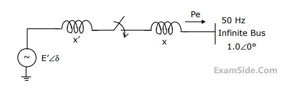
X1 = 0.1 pu, E1 = 1.0 pu, H = 5 MJ/MVA, mechanical power Pm = 0.0 pu, $$\omega $$B = 2 $$\pi \times $$50 rad/sec. All quantities are expressed on a common base.
The generator is initially running on open circuit with the frequency of the open circuit voltage slightly higher than that of the infinite bus. If at the instant of switch closure $$\delta = 0$$ and $$\omega = {{d\delta } \over {dt}} = {\omega _{init}},$$ compute the maximum value of $${\omega _{init}}$$ so that the generator pulls into synchronism.
$$\int {\left( {{{2H} \over {{\omega _B}}}} \right)\omega d\omega + {P_e}d\delta = 0} $$
2
GATE EE 2001
Subjective
+5
-0
A synchronous generator is connected to an infinite bus through a lossless double circuit transmission line. The generator is delivering 1.0 per unit power at a load angle of $${30^0}$$ when a sudden fault reduces the peak power that can be transmitted to 0.5 per unit. After clearance of fault, the peak power that can be transmitted becomes 1.5 per unit. Find the critical clearing angle.
3
GATE EE 2000
Subjective
+5
-0
A synchronous generator, having a reactance of 0.15 p.u., is connected to an infinite bus through two identical parallel transmission lines having reactance of 0.3 p.u. each. In steady state, the generator is delivering 1 p.u. Power to the infinite bus. For a three phase fault at the receiving end of one line, calculate the rotor angle at the end of first time step of 0.05 seconds. Assume the voltage behind transient reactance for the generator as 1.1 p.u. and infinite bus voltage as 1.0 p.u. Also indicate how the accelerating powers will be evaluated for the next time step if the breaker clears the fault.
(i) at the end of an interval
(ii) at the middle of an interval.
4
GATE EE 1998
Subjective
+5
-0
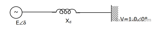
An alternator is connected to an infinite bus as shown in figure. It delivers 1.0 p.u. current at 0.8 p.f lagging at V = 1.0 p.u.. The reactance Xd of the alternator is 1.2 p.u. Determine the active power output and the steady state power limit. Keeping the active power fixed, if the excitation is reduced, find the critical excitation corresponding to operation at stability limit.
GATE EE Subjects
Browse all chapters by subject
Electric Circuits
Electrical Machines
Engineering Mathematics
Signals and Systems
Power Electronics
Power System Analysis
Digital Electronics
Analog Electronics
Electromagnetic Fields
Control Systems
Electrical and Electronics Measurement
General Aptitude