GATE ECE
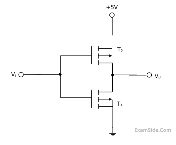
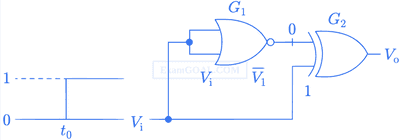
Statement 1: T1 conducts when Vi $$ \ge \,2\,V$$.
Statement 2: T1 is always in saturation when $${V_0}\, = \,0\,V$$.
Which of the following is correct?
q(s) = 2s5 + s4 + 4s3 + 2s2 + 2s + 1. The system is
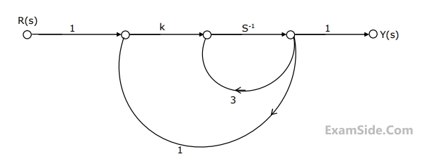
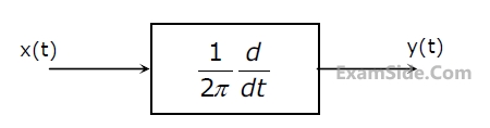
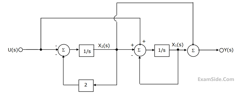 (a) Write down the state variable equations for the system in matrix form
assuming the state vector to be $${\left[ {{x_1}\left( t \right)\,\,{x_2}\left( t \right)} \right]^T}$$
(a) Write down the state variable equations for the system in matrix form
assuming the state vector to be $${\left[ {{x_1}\left( t \right)\,\,{x_2}\left( t \right)} \right]^T}$$
(b) Find out the state transition matrix.
(c) Determine y(t), t ≥ 0, when the initial values of the state at time t = 0 are $${x_1}$$(0) = 1, and $${x_2}$$(0) = 1.
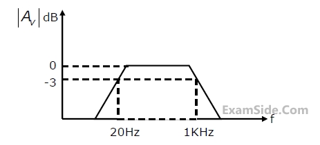
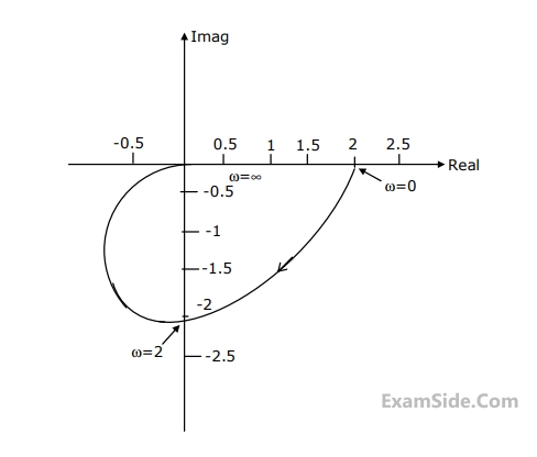
(a) Determine the frequency at which the plant has a phase lah of 90o.
(b) An intergral controller with transfer function Gc(s)=$${k \over s}$$ , isplaced in the forwardpath the value of k such that the compensated system has an open loop gain margin of 2.5.
(c) Determine the steady state errors of the compensated system to unit-step and unit-ramp inputs.
$$\mathop x\limits^ \bullet $$(t) = -2x(t)+2u(t)
y(t) = 0.5x(t) is
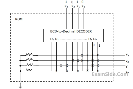
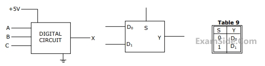 ( $$\overline A \,\overline B \,and\,\overline {C\,} $$ and are not available). The +5V power supply (logic 1) and the ground
(logic 0) are also available. The output of the circuit is X = $$\overline A \,B + \,\overline A \,\overline B \,\,\overline {C\,} $$
( $$\overline A \,\overline B \,and\,\overline {C\,} $$ and are not available). The +5V power supply (logic 1) and the ground
(logic 0) are also available. The output of the circuit is X = $$\overline A \,B + \,\overline A \,\overline B \,\,\overline {C\,} $$
(a) Write down the output function in its canonical SOP and POS forms.
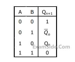
(b) Implement the circuit using only two 2:1 multiplexers shown in the Figure where S is the data-select line, $${D_0}\,$$ and $${D_1}\,$$ are the input data lines and Y is the output lines. The function table for the multiplexer is given in table

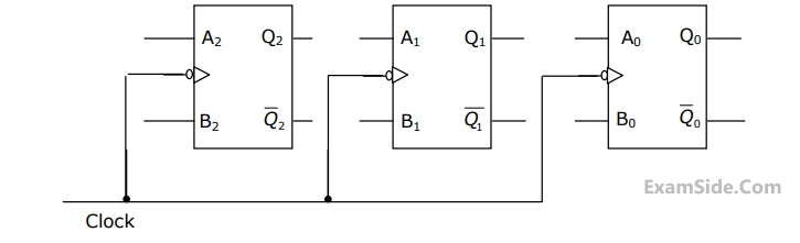
(a) Write down the state table for the mod-5 counter.
(b)Obtain simplified SOP expressions for the inputs A2, B2, A1, B1, A0 and B0 in terms of Q2, Q1, Q and their complements.
(c) Hence, complete the circuit diagram for the mod-5 counter given in the figure using minimum number of 2-input NAND-gate only.
This wave is
Where $$k = \,\,\eta \,\omega \,\, \in $$
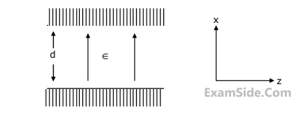
(a) Determine the surface charge densities $${\rho _s}$$ on the plates at x = 0 and x = d
(b) Determine the surface current densities $$\mathop {{J_s}}\limits^ \to $$ on the same plates.
(c) Prove that $${\rho _s}$$ and $$\mathop {{J_s}}\limits^ \to $$ satisfy the current continuity condition.
Where $$k = \,\,\eta \,\omega \,\, \in $$
(a) Determine the surface charge densities $${\rho _s}$$ on the plates at x = 0 and x = d
(b) Determine the surface current densities $$\mathop {{J_s}}\limits^ \to $$ on the same plates.
(c) Prove that $${\rho _s}$$ and $$\mathop {{J_s}}\limits^ \to $$ satisfy the current continuity condition.
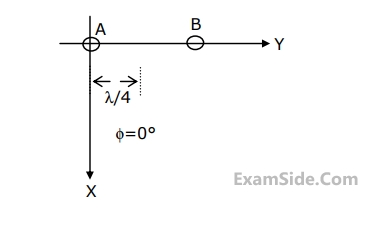
(a) Obtain the expression for the radiation pattern for E in the XY plane, i.e.,$$\left( {\theta = {{90}^0}} \right)$$.
(b) Sketch the radiation pattern obtained in (a).
Where $$k = \,\,\eta \,\omega \,\, \in $$
(a) Determine the surface charge densities $${\rho _s}$$ on the plates at x = 0 and x = d
(b) Determine the surface current densities $$\mathop {{J_s}}\limits^ \to $$ on the same plates.
(c) Prove that $${\rho _s}$$ and $$\mathop {{J_s}}\limits^ \to $$ satisfy the current continuity condition.
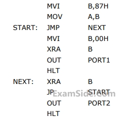 The execution of the above program in an 8085 microprocessor will result in
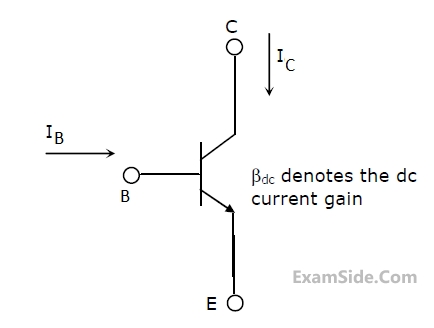
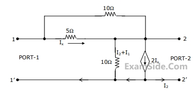
(a) Find its short-circuit admittance parameters.
(b) Find the open-ciruit impedance $${Z_{22}}$$.
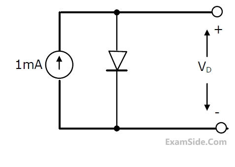
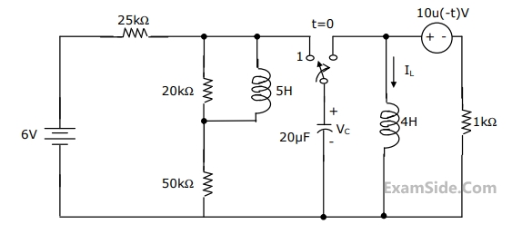
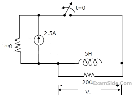
(a) Determine $${V_C}\left( {{0^ + }} \right)$$ and $${I_{_L}}\left( {{0^ + }} \right)$$
(b) Determine $${{d{V_C}\left( t \right)} \over {dt}}\,\,$$ at $$t\, = \,{0^ + }$$
(c) Determine $${{V_C}\left( t \right)}$$ for $$t > 0$$
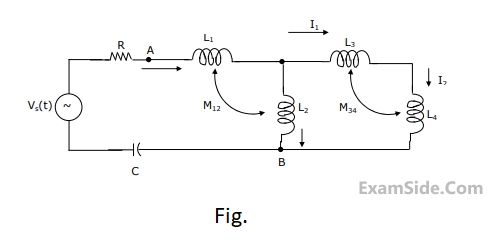
$${L_1} = 2\,H,\,{L_2} = 5\,H,\,{L_3}\, = \,1H,{L_4} = 4H\,\,\,$$ and $$C - 0.2\,\,\mu F.$$. The mutual inductances are $${M_{12}} = 3\,H$$ and $${M_{34}} = 2\,H$$.
Determine
(a) the equivalent inductance for the combination of $${L_3}$$ and $${L_4}$$,
(b) the equivalent inductance across the points A and B in the network,
(c) the resonant frequency of the network.
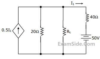
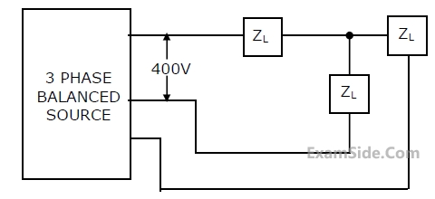
In the network of Figure, the maximum power is delivered to RL if its value is
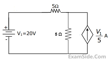
The dependent current source shown in Figure
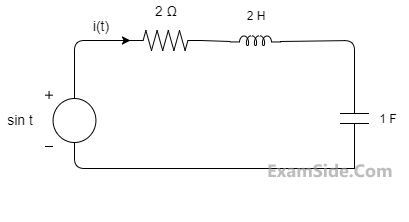
The differential equation for the current i(t) in the circuit of Fig. is
(a) Determine the autocorrelation Rxx ($$\tau $$) and the power spectral density Sxx(f).
(b) Find the output power spectral density Syy( f ).
(c) Evaluate Rxy(0) and Rxy(1/4).
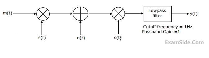
where $$x\left( t \right) = 10\,\,\cos \,\left( {8\pi \times {{10}^3}} \right)\,\,t$$ and
$${T_s} = 100\,\,\mu \sec .$$ When $$y\left( t \right)$$ is passed through an ideal low-pass filter with a cutoff frequency of 5 KHz, the output of the filter is
The output y(t) will be