1
GATE ECE 2000
Subjective
+5
-0
A certain linear, time-invariant system has the state and output representation shown below:
$$$\eqalign{
& \left[ {\matrix{
{\mathop {{x_1}}\limits^ \bullet } \cr
{\mathop {{x_2}}\limits^ \bullet } \cr
} } \right] = \left[ {\matrix{
{ - 2} & 1 \cr
0 & { - 3} \cr
} } \right]\left[ {\matrix{
{{x_1}} \cr
{{x_2}} \cr
} } \right] + \left[ {\matrix{
1 \cr
0 \cr
} } \right]u \cr
& y = \left( {\matrix{
1 & 1 \cr
} } \right)\left[ {\matrix{
{{x_1}} \cr
{{x_2}} \cr
} } \right] \cr} $$$
(a) Find the eigen values (natural frequencies) of the system.
(b)If u(t)=$$\delta \left( t \right)$$ and x1(0+)=x2(0+)=0, find x1(t),x2(t) and y(t), for t>0.
(c)When the input is zero, choose initial conditions $${x_1}\left( {{0^ + }} \right)$$ and $${x_2}\left( {{0^ + }} \right)$$ such that $$y\left( t \right) = A{e^{ - 2t}}$$ for t>0
2
GATE ECE 2000
Subjective
+5
-0
The operating conditions (ON = 1, OFF = 0) of three pumps (x,y,z) are to be
monitored. x = 1 implies that pump X is on. It is required that the indicator (LED)
on the panel should glow when a majority of the pumps fail.
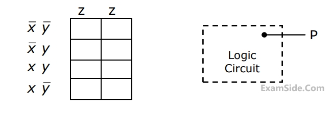
(a) Enter the logical values in the K-map in the format shown in figure 3(a). Derive
the minimal Boolean sum-of-products expression whose output is zero when a majority of the pumps fail.
(b) The above expression is implemented using logic gates, and point P is the
output of this circuit, as shown in figure 3(b). P is at 0 V when a majority of the pumps fails and is at 5 V otherwise. Design a circuit to drive the LED using this output. The current through the LED should be 10 mA and the voltage drop across it is 1V. Assume that P can source or sink 10 mA and a 5 V supply is available.
3
GATE ECE 2000
MCQ (Single Correct Answer)
+2
-0.6
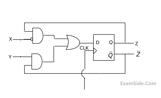
A sequential circuit using D flip-flop and logic gates is shown in the figure, where X and Y are the inputs and Z is the output. The circuit is
4
GATE ECE 2000
MCQ (Single Correct Answer)
+2
-0.6
In the figure, the J and K inputs of all the four Flip-Flops are made high. The frequency of the signal at output Y is 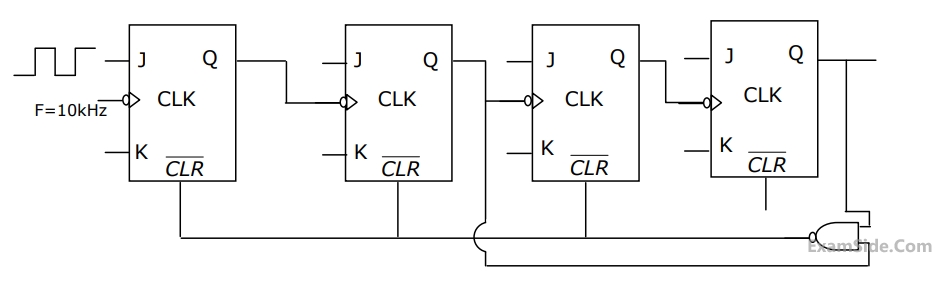
Paper Analysis
Total Questions
Analog Circuits 8
Communications 2
Control Systems 6
Digital Circuits 7
Electromagnetics 8
Engineering Mathematics 3
Microprocessors 2
Network Theory 10
Signals and Systems 9
More Papers of GATE ECE
GATE ECE 2026 GATE ECE 2025 GATE ECE 2024 GATE ECE 2023 GATE ECE 2022 GATE ECE 2021 GATE ECE 2020 GATE ECE 2019 GATE ECE 2018 GATE ECE 2017 Set 1 GATE ECE 2017 Set 2 GATE ECE 2016 Set 1 GATE ECE 2016 Set 2 GATE ECE 2016 Set 3 GATE ECE 2015 Set 3 GATE ECE 2015 Set 1 GATE ECE 2015 Set 2 GATE ECE 2014 Set 1 GATE ECE 2014 Set 3 GATE ECE 2014 Set 4 GATE ECE 2014 Set 2 GATE ECE 2013 GATE ECE 2012 GATE ECE 2011 GATE ECE 2010 GATE ECE 2009 GATE ECE 2008 GATE ECE 2007 GATE ECE 2006 GATE ECE 2005 GATE ECE 2004 GATE ECE 2003 GATE ECE 2002 GATE ECE 2001 GATE ECE 2000 GATE ECE 1999 GATE ECE 1998 GATE ECE 1997 GATE ECE 1996 GATE ECE 1995 GATE ECE 1994 GATE ECE 1993 GATE ECE 1992 GATE ECE 1991 GATE ECE 1990 GATE ECE 1989 GATE ECE 1988 GATE ECE 1987
GATE ECE Papers
All year-wise previous year question papers
2026
2025
2024
2023
2022
2021
2020
2019
2018
2013
2012
2011
2010
2009
2008
2007
2006
2005
2004
2003
2002
2001
2000
1999
1998
1997
1996
1995
1994
1993
1992
1991
1990
1989
1988
1987