1
GATE EE 1999
Subjective
+5
-0
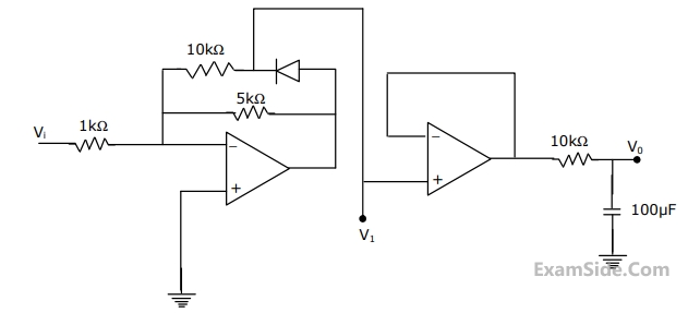
The input voltage $${V_i}$$ in the circuit is a $$1$$ $$kHz$$ sine wave of $$1$$ $$V$$ amplitude. Assume ideal operational amplifiers with $$ \pm 15V\,\,DC$$ supply. Sketch on a single diagram the wave-forms of $${V_i},$$ $${V_1}$$ and $${V_0}$$ show, indicating the peak value of$${V_1}$$ and the average value $${V_0}$$.
2
GATE EE 1998
Subjective
+5
-0
In the circuit of figure $${R_s} = 2\,k\Omega ,$$ $${R_L} = 5\,k\Omega $$ For the op-amp $$A = {10^5},$$
$${R_i} = 100\,k\Omega ,\,\,{R_0} = 50\,k\Omega .$$ For $${V_0} = 10V.$$
Calculate $${V_S}$$ and $${{{V_0}} \over {{V_S}}}$$ and estimate the input resistance of the circuit,
$${R_i} = 100\,k\Omega ,\,\,{R_0} = 50\,k\Omega .$$ For $${V_0} = 10V.$$
Calculate $${V_S}$$ and $${{{V_0}} \over {{V_S}}}$$ and estimate the input resistance of the circuit,
3
GATE EE 1994
Subjective
+5
-0
Figure below shows an op-amp amplifier. Find the output voltage in steady state condition where $$(i)$$ switch is open $$(ii)$$ $$S$$ is closed

4
GATE EE 1992
Subjective
+5
-0
$$(a)$$ For the circuit shown in figure

$$(i)$$ Calculate the transfer function $${{{V_0}} \over {{V_i}}}$$
$$(ii)$$ plot the amplitude and phase response as a function for $$R = {R_1}$$
GATE EE Subjects
Browse all chapters by subject
Electric Circuits
Electrical Machines
Engineering Mathematics
Signals and Systems
Power Electronics
Power System Analysis
Digital Electronics
Analog Electronics
Electromagnetic Fields
Control Systems
Electrical and Electronics Measurement
General Aptitude