GATE EE


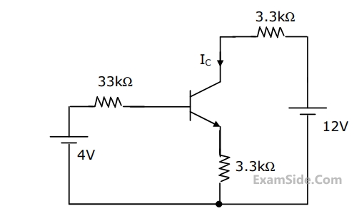
The value of collector current $${{\rm I}_C}$$ of the transistor is approximately


The above equation may be organized in the state space form as follows
$$\left( {\matrix{
{{{{d^2}\omega } \over {d{t^2}}}} \cr
{{{d\omega } \over {dt}}} \cr
} } \right) = P\left( {\matrix{
{{{d\omega } \over {dt}}} \cr
\omega \cr
} } \right) + Q{V_a}$$
where the $$P$$ matrix is given by
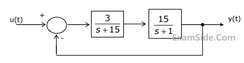
The response of the system as $$\,t \to \infty $$ is
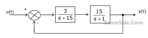

The natural time constants of the response of the system are

$$\eqalign{ & LXI\,\,\,\,\,\,\,\,\,\,\,\,\,\,\,\,\,\,\,\,\,\,\,\,\,\,\,H,\,\,\,1FFE \cr & MOV\,\,\,\,\,\,\,\,\,\,\,\,\,\,\,\,\,\,\,\,\,\,\,B,\,\,\,M \cr & INR\,\,\,\,\,\,\,\,\,\,\,\,\,\,\,\,\,\,\,\,\,\,\,\,\,\,\,\,L \cr & MOV\,\,\,\,\,\,\,\,\,\,\,\,\,\,\,\,\,\,\,\,\,\,\,\,A,\,\,\,M \cr & ADD\,\,\,\,\,\,\,\,\,\,\,\,\,\,\,\,\,\,\,\,\,\,\,\,\,B \cr & INR\,\,\,\,\,\,\,\,\,\,\,\,\,\,\,\,\,\,\,\,\,\,\,\,\,\,\,\,L \cr & MOV\,\,\,\,\,\,\,\,\,\,\,\,\,\,\,\,\,\,\,\,\,\,\,\,M,\,\,\,A \cr & XRA\,\,\,\,\,\,\,\,\,\,\,\,\,\,\,\,\,\,\,\,\,\,\,\,\,\,\,A \cr} $$
On completion of the execution of the program, the result of additional is found.


$$\left[ {\matrix{ {{E_1}} \cr {{{\rm I}_2}} \cr } } \right] = \left[ {\matrix{ {{h_{11}}} & {{h_{12}}} \cr {{h_{21}}} & {{h_{22}}} \cr } } \right]\left[ {\matrix{ {{{\rm I}_1}} \cr {{E_2}} \cr } } \right].$$
For the two $$-$$ port network shown in Fig. the value of $${h_{12}}$$ is given by


List $$-$$ $${\rm I}$$
$$A.$$ Resistance in the milli Ohm range
$$B.$$ Low values of Capacitance
$$C.$$ Comparison of resistances which are nearly equal
$$D.$$ Inductance of a coil with a large time $$-$$ constant
List $$-$$ $${\rm II}$$
$$1.$$ Wheatstone Bridge
$$2.$$ Kelvin Double Bridge
$$3.$$ Schering Bridge
$$4.$$ Wien's Bridge
$$5.$$ Hay's Bridge
$$6.$$ Carry $$-$$ Foster Bridge

P. Stator winding current is dc, rotor-winding current is ac
Q. Stator winding current is ac, rotor-winding current is dc
R. Stator winding current is ac, rotor-winding current is ac
S. Stator has salient poles and rotor has commutator
T. Rotor has salient poles and sliprings and stator is cylindrical
U. Both stator and rotor have poly-phase windings
DC machines. Synchronous machines and Induction machines exhibit some of the above properties as given in the following table. Indicate the correct combination from this table
 The following Table gives four sets of statements as regards poles and torque.
Select the correct set corresponding to the mmf axes as shown in Figure.
The following Table gives four sets of statements as regards poles and torque.
Select the correct set corresponding to the mmf axes as shown in Figure.P. The difference between synchronous speed and actual speed remains same
Q. The air-gap flux remains same
R. The stator current remains same
S. The p.u. slip remains same
Among the above, correct statements are


Group I
P. Food mixer
Q. Cassette tape recorder
R. Domestic water pump
S. Escalator
Group II
1. Permanent magnet dc motor
2. Single phase induction motor
3. Universal motor
4. Three phase induction motor
5. DC series motor
6. Stepper motor
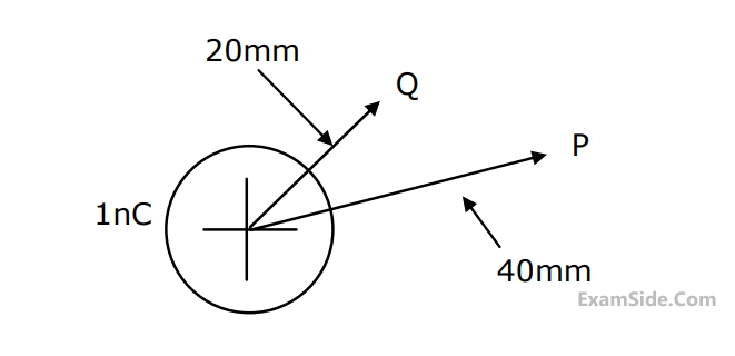
The magnetic field intensity $$\overrightarrow H $$ at point $$P$$ is


When the conduction angle $$\alpha = {120^0},$$ the $$rms$$ fundamental component of the output voltage is
With reference to the output waveform given in figure, the output of the converter will be free form $${5^{th}}$$ harmonic when

The output $$dc$$ voltage wave shape will be as shown in


(a) Calculate the voltage on the line-end unit.
(b) Calculate the value of capacitance $${C_x}$$ required.
$${\rm I}{C_1} = 20 + 0.3\,\,{P_1},\,{\rm I}{C_2} = 30 + 0.4\,\,{P_2},\,{\rm I}{C_3} = 30$$
Assume that all the three units are operating all the time. Minimum and maximum loads on each unit are $$50$$ $$MW$$ and $$300$$ $$MW$$ respectively. If the plant is operating on economic load dispatch to supply the total power demand of $$700$$ $$MW$$, the power generated by each unit is

List-$${\rm I}$$
$$A.$$ Distance relay
$$B.$$ Under frequency relay
$$C.$$ Differential relay
$$D.$$ Buchholz relay
$$1.$$ Transformers
$$2.$$ Turbines
$$3.$$ Busbars
$$4.$$ Shunt capacitors
$$5.$$ Alternators
$$6.$$ Transmission lines
A branch having an impedance of $$j0.2\Omega $$ is connected between bus $$2$$ and the reference. Then the values of $${Z_{22,new}}$$ and $${Z_{23,new}}$$ of the bus impedance matrix of the modified network are respectively
$$1.$$ D.C. line inductor
$$2.$$ A.C. line inductor
$$3.$$ Reactive power sources
$$4.$$ Distance relays on D.C. line
$$5.$$ Series capacitance of A.C. line
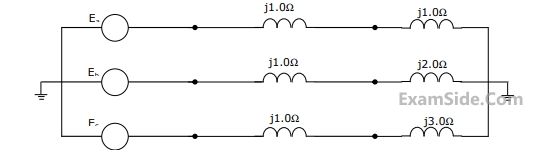
$${E_a} = 10\angle {0^ \circ }V,\,\,\,{E_b} = 10\angle - {90^ \circ }V,\,\,{E_c} = 10\angle {120^ \circ }\,\,V.\,\,\,\,$$ The positive sequence component of the load current is