GATE EE 2013
View Questions

GATE EE

1
In the circuit shown below, the knee current of the ideal Zener diode is $$10$$ $$mA.$$ To maintain $$5 V$$ across $${R_L}$$, the minimum value of $${R_L}$$ in $$\Omega $$ and the minimum power rating of the Zener diode in $$mW$$ respectively are GATE EE 2013 Analog Electronics - Diode Circuits and Applications Question 15 English
2
A voltage $$1000\sin \omega t$$ Volts is applied across $$YZ.$$ Assuming ideal diodes, the voltage measured across $$WX$$ in Volts is GATE EE 2013 Analog Electronics - Diode Circuits and Applications Question 14 English
3
In the circuit shown below what is the output voltage $$\left( {{V_{out}}} \right)$$ in Volts If a silicon transfer $$Q$$ and an ideal op-amp are used? GATE EE 2013 Analog Electronics - Operational Amplifier Question 58 English
4
In the circuit shown below the op-amps are ideal. Then $${V_{out}}$$ in Volts is GATE EE 2013 Analog Electronics - Operational Amplifier Question 24 English
5
In the feedback network shown below, if the feedback factor $$k$$ is increased, then the GATE EE 2013 Analog Electronics - Feedback Amplifiers and Oscillator Circuits Question 9 English
6
The state variable formulation of a system is given as
$$\left[ {\matrix{ {\mathop {{x_1}}\limits^ \bullet } \cr {\mathop {{x_2}}\limits^ \bullet } \cr } } \right] = \left[ {\matrix{ { - 2} & 0 \cr 0 & { - 1} \cr } } \right]\left[ {\matrix{ {{x_1}} \cr {{x_2}} \cr } } \right] + \left[ {\matrix{ 1 \cr 1 \cr } } \right]u,\,\,{x_1}\left( 0 \right) = 0,$$
$${x_2}\left( 0 \right) = 0$$ and $$y = \left[ {\matrix{ 1 & 0 \cr } } \right]\left[ {\matrix{ {{x_1}} \cr {{x_2}} \cr } } \right]$$

The response $$y(t)$$ to a unit step input is

7
The transfer function $${{{V_2}\left( s \right)} \over {{V_1}\left( s \right)}}$$ of the circuit shown below is GATE EE 2013 Control Systems - Basics of Control System Question 6 English
8
The signal flow graph for a system is given below. The transfer function $${{Y\left( s \right)} \over {U\left( s \right)}}$$ for this system is GATE EE 2013 Control Systems - Block Diagram and Signal Flow Graph Question 8 English
9
The open-loop transfer function of a $$dc$$ motor is given as $${{\omega \left( s \right)} \over {{V_a}\left( s \right)}} = {{10} \over {1 + 10s}}.$$ When connected in feedback as shown below, the approximate value of $${K_a}$$ that will reduce the time constant of the closed loop system by one hundred times as compared to that of the open-loop system is GATE EE 2013 Control Systems - Time Response Analysis Question 12 English
10
The Bode plot of a transfer function $$G(s)$$ is shown in the figure below. GATE EE 2013 Control Systems - Polar Nyquist and Bode Plot Question 41 English

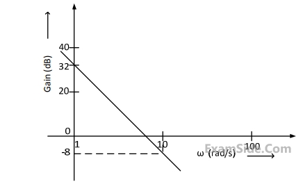
The gain is $$\left( {20\log \left| {G\left( s \right)} \right|} \right)$$ is $$32$$ $$dB$$ and $$–8$$ $$dB$$ at $$1$$ $$rad/s$$ and $$10$$ $$rad/s$$ respectively. The phase is negative for all $$\omega .$$ Then $$G(s)$$ is

11
The state variable formulation of a system is given as
$$\left[ {\matrix{ {\mathop {{x_1}}\limits^ \bullet } \cr {\mathop {{x_2}}\limits^ \bullet } \cr } } \right] = \left[ {\matrix{ { - 2} & 0 \cr 0 & { - 1} \cr } } \right]\left[ {\matrix{ {{x_1}} \cr {{x_2}} \cr } } \right] + \left[ {\matrix{ 1 \cr 1 \cr } } \right]u,\,\,{x_1}\left( 0 \right) = 0,$$
$${x_2}\left( 0 \right) = 0$$ and $$y = \left[ {\matrix{ 1 & 0 \cr } } \right]\left[ {\matrix{ {{x_1}} \cr {{x_2}} \cr } } \right]$$

The system is

12
A bulb in staircase has two switches, one switch being at the ground floor and the other one at the first floor. The bulb can be turned $$ON$$ and also can be turned $$OFF$$ by any one of the switches irrespective of the state of the other switch. The logic of switching of the bulb resembles
13
The clock frequency applied to the digital circuit shown in the figure below is $$1$$ $$kHz.$$ If the initial state of the output $$Q$$ of the flip-flop is $$‘0’,$$ then the frequency of the output waveform $$Q$$ in $$kHz$$ is GATE EE 2013 Digital Electronics - Sequential Circuits Question 13 English
14
Three capacitors C1, C2 and C3 whose values are 10μF, 5μF and 2μF respectively, have breakdown voltages of 10V, 5V and 2V respectively. For the interconnection shown, the maximum safe voltage in Volts that can be applied across the combination and the corresponding total charge in μC stored in the effective capacitance across the terminals are respectively GATE EE 2013 Electric Circuits - Network Elements Question 39 English
15
A source $$v_s\left(t\right)=V\cos100\mathrm{πt}$$ has an internal impedance of (4 + j3) Ω.If a purely resistive load connected to this source has to extract the maximum power out of the source, its value in Ω should be
16
In the circuit shown below, if the source voltage $$V_s=100\angle53.12^\circ\;V$$ then the Thevenin’s equivalent voltage in Volts as seen by the load resistance RL is GATE EE 2013 Electric Circuits - Network Theorems Question 23 English
17
Two magnetically uncoupled inductive coils have Q factors q1 and q2 at the chosen operating frequency. Their respective resistances are R1 and R2 . When connected in series, their effective Q factor at the same operating frequency is
18
Consider a delta connection of resistors and it's equivalent star connection as shown below. If all elements of the delta connection are scaled by a factor k, k>0, the elements of the corresponding star equivalent will be scaled by a factor of GATE EE 2013 Electric Circuits - Network Elements Question 48 English
19
The input impedance of the permanent magnet moving coil $$(PMMC)$$ voltmeter is infinite. Assuming that the diode shown in the figure below is ideal, the reading of the voltmeter in Volts is GATE EE 2013 Electrical and Electronics Measurement - Basic of Indicating Instruments Question 26 English
20
Three moving iron type voltmeters are connected as shown below. Voltmeter readings are $$V,$$ $${V_1}$$ and $${V_2}$$ , as indicated. The correct relation among the voltmeter readings is GATE EE 2013 Electrical and Electronics Measurement - Basic of Indicating Instruments Question 25 English
21
A strain gauge forms one arm of the bridge shown in the figure below and has a nominal resistance without any load as $$\,{R_s} = 300\Omega .$$ Other bridge resistance are $$\,{R_1} = {R_2} = {R_3} = 300\Omega .\,\,$$ The maximum permissible current through the strain gauge is $$20$$ $$mA.$$ During certain measurement when the bridge is excited by maximum permissible voltage and the strain gauge resistance is increased by $$1$$% over the nominal value, the output voltage $${V_0}$$ in $$mV$$ is GATE EE 2013 Electrical and Electronics Measurement - Measurement of Resistance and A.C Bridges Question 6 English
22
A single-phase transformer has no-load loss of 64 W, as obtained from an open circuit test. When a short-circuit test is performed on it with 90% of the rated currents flowing in its both LV and HV windings, he measured loss is 81 W. The transformer has maximum efficiency when operated at
23
The following arrangement consists of an ideal transformer and an attenuator which attenuates by a factor of 0.8. An ac voltage VWX1 = 100V is applied across WX to get an open circuit voltage VYZ1 across YZ. Next, an ac voltage VYZ2 =100V is applied across YZ to get an open circuit voltage VWX2 across WX. Then, $$\frac{V_{YZ1}}{V_{WX1}}$$, $$\frac{V_{WX2}}{V_{YZ2}}$$ are respectively, GATE EE 2013 Electrical Machines - Transformers Question 60 English
24
Leakage flux in an induction motor is
25
A 4-pole induction motor, supplied by a slightly unbalanced three-phase 50Hz source, is rotating at 1440 rpm. The electrical frequency in Hz of the induced negative sequence current in the rotor is
26
A dielectric slab with 500 mm x 500 mm cross-section is 0.4 m long. The slab is subjected to a uniform electric field of $$E=6{\widehat a}_x+8{\widehat a}_y$$ kV /mm. The relative permittivity of the dielectric material is equal to 2. The value of constant $$\varepsilon_0$$ is $$8.85\times10^{-12}\;F/m$$ . The energy stored in the dielectric in Joules is
27
The flux density at a point in space is given by $$\overrightarrow B=\;4x{\widehat a}_x\;+\;2ky{\widehat a}_y\;+\;8{\widehat a}_z\;\;Wb/m^2$$. The value of constant k must be equal to
28
Square roots of $$-i,$$ where $$i = \sqrt { - 1} $$ are
29
$$\oint {{{{z^2} - 4} \over {{z^2} + 4}}} dz\,\,$$ evaluated anticlockwise around the circular $$\left| {z - i} \right| = 2,$$ where $$i = \sqrt { - 1} $$, is
30
The equation $$\left[ {\matrix{ 2 & { - 2} \cr 1 & { - 1} \cr } } \right]\left[ {\matrix{ {{x_1}} \cr {{x_2}} \cr } } \right] = \left[ {\matrix{ 0 \cr 0 \cr } } \right]$$ has
31
A matrix has eigen values $$-1$$ and $$-2.$$ The corresponding eigenvectors are $$\left[ {\matrix{ 1 \cr { - 1} \cr } } \right]$$ and $$\left[ {\matrix{ 1 \cr { - 2} \cr } } \right]$$ respectively. The matrix is
32
A function $$y = 5{x^2} + 10x\,\,$$ is defined over an open interval $$x=(1,2).$$ At least at one point in this interval, $${{dy} \over {dx}}$$ is exactly
33
The curl of the gradient of the scalar field defined by $$\,V = 2{x^2}y + 3{y^2}z + 4{z^2}x$$ is
34
Given a vector field $$\overrightarrow F = {y^2}x\widehat a{}_x - yz\widehat a{}_y - {x^2}\widehat a{}_z,$$ the line integral $$\int {F.dl} $$ evaluated along a segment on the $$x-$$axis from $$x=1$$ to $$x=2$$ is
35
A continuous random variable $$X$$ has a probability density function $$f\left( x \right) = {e^{ - x}},0 < x < \infty .$$ Then $$P\left\{ {X > 1} \right\}$$ is
36
When the Newton-Raphson method is applied to solve the equation $$\,\,f\left( x \right) = {x^3} + 2x - 1 = 0,\,\,$$ the solution at the end of the first iteration with the initial value as $${x_0} = 1.2$$ is
37
Thyristor $$T$$ in the figure below is initially off and is triggered with a single pulse of width $$10\mu s.$$ It is given that $$L = \left( {{{100} \over \pi }} \right)\mu H$$ and $$C = \left( {{{100} \over \pi }} \right)\mu F.$$ Assuming latching and holding currents of the thyristor are both zero and the initial charge on $$C$$ is zero, $$T$$ conducts for GATE EE 2013 Power Electronics - Power Semiconductor Devices Question 10 English
38
In the figure shown below, the chopper feeds a resistive load from a battery source. $$MOSFET$$ $$Q$$ is switched at $$250$$ $$kHz,$$ with a duty ratio of $$0.4.$$ All elements of the circuit are assumed to be ideal. GATE EE 2013 Power Electronics - Choppers and Commutation Techniques Question 25 English

The average source current in Amps in steady-state is

39
In the figure shown below, the chopper feeds a resistive load from a battery source. $$MOSFET$$ $$Q$$ is switched at $$250$$ $$kHz,$$ with a duty ratio of $$0.4.$$ All elements of the circuit are assumed to be ideal. GATE EE 2013 Power Electronics - Choppers and Commutation Techniques Question 24 English

The PEAK-TO-PEAK source current ripple in $$Amps$$ is

40
The Voltage Source Inverter $$(VSI)$$ shown in the figure below is switched to provide a $$50$$ $$Hz,$$ square-wave $$ac$$ output voltage ($${V_0}$$) across an $$R$$-$$L$$ load. Reference polarity of $${V_0}$$ and reference direction of the output current $${I_0}$$ are indicated in the figure. It is given that $$R = 3\,\,\Omega ,\,\,L = 9.55\,\,mH.$$ GATE EE 2013 Power Electronics - Inverters Question 11 English

Appropriate transition $$i.e,,$$ $$Zero$$ voltage switching $$(ZVS)/Zero$$ current switching $$(ZCS)$$ of the $$IGBTs$$ during turn - on/turn off is

41
The Voltage Source Inverter $$(VSI)$$ shown in the figure below is switched to provide a $$50$$ $$Hz,$$ square-wave $$ac$$ output voltage ($${V_0}$$) across an $$R$$-$$L$$ load. Reference polarity of $${V_0}$$ and reference direction of the output current $${I_0}$$ are indicated in the figure. It is given that $$R = 3\,\,\Omega ,\,\,L = 9.55\,\,mH.$$ GATE EE 2013 Power Electronics - Inverters Question 12 English

In the interval when $${V_0} < 0$$ and $${i_0} > 0$$ the pair of devices which conducts the load current is

42
For a power system network with $$n$$ nodes, $${Z_{33}}$$ of its bus impedance matrix is $$j0.5$$ per unit. The voltage at mode $$3$$ is $$1.3\angle - {10^0}\,\,$$ per unit. If a capacitor having reactance of $$-j3.5$$ per unit is now added to the network between node $$3$$ and the reference node, the current drawn by the capacitor per unit as
43
In the following network, the voltage magnitudes at all buses are equal to $$1$$ p.u., the voltage phase angles are very small, and the line resistance are negligible. All the line reactances are equal to $$j1\Omega .$$ GATE EE 2013 Power System Analysis - Load Flow Studies Question 10 English

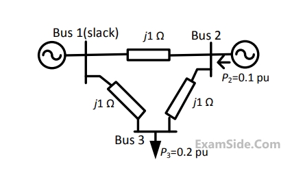
The voltage phase angles in rad at buses $$2$$ and $$3$$ are

44
In the following network, the voltage magnitudes at all buses are equal to $$1$$ p.u., the voltage phase angles are very small, and the line resistance are negligible. All the line reactances are equal to $$j1\Omega .$$ GATE EE 2013 Power System Analysis - Load Flow Studies Question 9 English

If the base impedance and the line-to-line base voltage are $$100\Omega $$ and $$\,100kV,\,\,$$ respectively, then the real power in MW delivered by the generator connected at the slack bus is

45
The angle $$\delta $$ in the swing equation of a synchronous generator is the
46
A single load is supplied by a single voltage source. If the current flowing from the load to the source is $$10\angle - {150^0}$$ A and if the voltage at the load terminals is $$100\angle {60^0}$$ $$V,$$ then the
47
Which one of the following statements is NOT TRUE for a continuous time causal and stable LTI system?
48
For a periodic signal the $$v\left(t\right)=30\sin100t\;+\;10\cos300t\;+\;6\sin\left(500t\;+\;\frac{\mathrm\pi}4\right)$$ fundamental frequency in radians/s is
49
The impulse response of a system is h(t) = tu(t). For an input u(t − 1), the output is
50
Assuming zero initial condition, the response y(t) of the system given below to a unit step input u(t) is GATE EE 2013 Signals and Systems - Linear Time Invariant Systems Question 45 English
51
Two systems with impulse responses h1(t) and h2(t) are connected in cascade. Then the overall impulse response of the cascaded system is given by
52
The impulse response of a continuous time system is given by h(t) = $$\delta$$(t − 1) + $$\delta$$(t − 3). The value of the step response at t = 2 is
53
A band-limited signal with a maximum frequency of 5 kHz is to be sampled. According to the sampling theorem, the sampling frequency in kHz which is not valid is
EXAM MAP
Medical
NEETAIIMS
Graduate Aptitude Test in Engineering
GATE CSEGATE ECEGATE EEGATE MEGATE CEGATE PIGATE IN
Civil Services
UPSC Civil Service
Defence
NDA
Staff Selection Commission
SSC CGL Tier I
CBSE
Class 12