GATE EE 2007
View Questions

GATE EE

1
$$IC$$ $$555$$ in the adjacent figure is configured as an Astable multivibrator. It is enabled to oscillator at $$t=0$$ by applying a high input to pin $$4.$$ The pin description is $$1$$ and $$8$$ $$-$$supply; $$2-$$trigger; $$4-$$reset; $$6$$-threshold; $$7$$-discharge. The wave form appearing across the capacitor starting from $$t=0$$ as observed on the storage $$CRO$$ is GATE EE 2007 Analog Electronics - 555 Timer Question 2 English
2
The switch $$'S'$$ is the circuit of the figure is initially closed. It is opened at time $$t=0.$$ You may neglect the zener diode forward voltage drops. What is the behavior of $${V_{OUT}}$$ for $$t > 0$$ GATE EE 2007 Analog Electronics - Operational Amplifier Question 29 English
3
The input signal $${V_{in}}$$ shown in the figure is a $$1$$ $$kHz$$ square wave voltage that alternates between $$+7V$$ and $$-7V$$ with a $$50\% $$ duty cycle. Both transistors have the same current gain, which is large. The circuit delivers power to the load resistor $${R_L}.$$ What is the efficiency of this circuit for the given input? Choose the closest answer. GATE EE 2007 Analog Electronics - Operational Amplifier Question 28 English
4
The circuit shown in figure is GATE EE 2007 Analog Electronics - Operational Amplifier Question 47 English
5
The three terminal linear voltage regular is connected to a $$10\Omega $$ load resistor as shown in the figure. If $${V_{in}}$$ is $$10$$ $$V,$$ what is the power dissipated in the transistor GATE EE 2007 Analog Electronics - Bjt and Mosfet Biasing Question 6 English
6
The common emitter forward current gain of the transistor shown is $${\beta _p} = 100.$$ The transistor is operating in GATE EE 2007 Analog Electronics - Bjt and Mosfet Biasing Question 7 English
7
$$R-L-C$$ circuit shown in figure GATE EE 2007 Control Systems - Time Response Analysis Question 4 English

If the above step response is to be observed on a non - storage $$CRO,$$ then it would be best have the $${e_i}$$ as a

8
The system $$900/s(s+1)(s+9)$$ is to be such that its gain crossover frequency becomes same as its uncompensated phase crossover frequency and provides at $${45^0}$$ phase margin . To achieve this, one may use
9
If $$X = {\mathop{\rm Re}\nolimits} G\left( {j\omega } \right),\,\,$$ and $$y = {\rm I}mG\left( {j\omega } \right)$$ then for $$\omega \to {0^ + },\,\,$$ the Nyquist plot for $$G\left( s \right) = 1/\left[ {s\left( {s + 1} \right)\left( {s + 2} \right)} \right]$$
10
Consider the feedback system shown below which is subjected to a unit step input. The system is stable and has following parameters $${k_p} = 4,\,\,{k_i} = 10,\,\,\omega = 500\,\,$$ and $$\xi $$ $$=0.7.$$ The steady state value of $$z$$ is GATE EE 2007 Control Systems - Time Response Analysis Question 6 English
11
$$R-L-C$$ circuit shown in figure GATE EE 2007 Control Systems - Time Response Analysis Question 5 English

For a step input $${e_{i,}}$$ the overshoot in the output $${e_{0,}}$$ will be

12
The system shown in the figure is GATE EE 2007 Control Systems - Routh Hurwitz Stability Question 3 English
13
If the loop gain $$K$$ of a negative feedback system having a loop transfer function $$K\left( {s + 3} \right)/{\left( {s + 8} \right)^2}$$ is to be adjusted to induce a sustained oscillation then
14
The system shown in figure below GATE EE 2007 Control Systems - Block Diagram and Signal Flow Graph Question 3 English 1
can be reduced to the form GATE EE 2007 Control Systems - Block Diagram and Signal Flow Graph Question 3 English 2
With
15
The associated figure shows the two types of rotate right instruction $${R_1},\,{R_2}$$ available in a microprocessor where Register is a $$8$$-bit register and $$C$$ is the carry bit. The rotate left instructions $$L1$$ and $$L2$$ are similar except that $$C$$ now links the most significant bit of Register instead of the least significant one. GATE EE 2007 Digital Electronics - Microprocessor Question 10 English

Such a division can be correctly performed by the following set of operations

16
The associated figure shows the two types of rotate right instruction $${R_1},\,{R_2}$$ available in a microprocessor where Register is a $$8$$-bit register and $$C$$ is the carry bit. The rotate left instructions $$L1$$ and $$L2$$ are similar except that $$C$$ now links the most significant bit of Register instead of the least significant one. GATE EE 2007 Digital Electronics - Microprocessor Question 11 English

Suppose Register contains the $$2's$$ complement number $$11010110.$$ If this number is delivered by $$2$$ the answer should be

17
Which one of the following statements regarding the $$INT$$ (interrupt) and the $$BRQ$$ (bus request) pins in a $$CPU$$ is true?
18
In an $$8085$$ $$A$$ microprocessor based system, it is desired to increment the contents of memory location whose address is available in $$(D,E)$$ register pair and store the result in same location. The sequence of instructions is
19
$$A,B,C$$ and $$D$$ are input bits, and $$Y$$ is the output bit in the $$XOR$$ gate circuit of the figure below. Which of the following statements about the sum $$S$$ of $$A,B,C,D$$ and $$Y$$ is correct? GATE EE 2007 Digital Electronics - Logic Gates Question 2 English
20
A $$3$$ $$V$$ $$dc$$ supply with an internal resistance of $$2$$ $$\Omega $$ supplies a passive non-linear resistance characterized by the relation $${V_{NL}} = {{\rm I}^2}{}_{NL}$$. The power dissipated in the non-linear resistance is
21
The matrix $$A$$ given below is the node incidence matrix of a network. The columns correspond to braches of the network while the rows correspond to nodes. Let
$$V = {\left[ {{v_1}\,\,{v_2}....{v_6}} \right]^T}$$ denote the vector of branches voltages while
$${\rm I} = {\left[ {{i_1}\,{i_2}....{i_6}} \right]^T}$$ that of branch currents. The vector $$E = {\left[ {{e_1}\,{e_2}\,\,{e_3}\,{e_4}} \right]^T}$$ denotes the vector of node voltages relative to a common ground. $$$A = \left[ {\matrix{ 1 & 1 & 1 & 0 & 0 & 0 \cr 0 & { - 1} & 0 & { - 1} & 1 & 0 \cr { - 1} & 0 & 0 & 0 & { - 1} & { - 1} \cr 0 & 0 & { - 1} & 1 & 0 & 1 \cr } } \right]$$$

Which of the following statements is true?

22
A three phase balanced star connected voltage source with frequency $$\omega \,\,rad/s$$ is connected to a star connected balanced load which is purely inductive. The instantaneous line currents and phase to neutral voltages are denoted by $$\left( {{i_a},{i_b},{i_c}} \right)$$ and $$\left( {{V_{an}},\,\,{V_{bn}},\,\,{V_{cn}}} \right)$$ respectively and their $$rms$$ values are denoted by $$V$$ and $$1.$$ If $$$R = \left[ {{V_{an}}\,\,{V_{bn}}\,\,{V_{cn}}} \right]\left[ {\matrix{ 0 & {{1 \over {\sqrt 3 }}} & { - {1 \over {\sqrt 3 }}} \cr { - {1 \over {\sqrt 3 }}} & 0 & {{1 \over {\sqrt 3 }}} \cr {{1 \over {\sqrt 3 }}} & { - {1 \over {\sqrt 3 }}} & 0 \cr } } \right]\left[ {\matrix{ {{i_a}} \cr {{i_b}} \cr {{i_c}} \cr } } \right],$$$
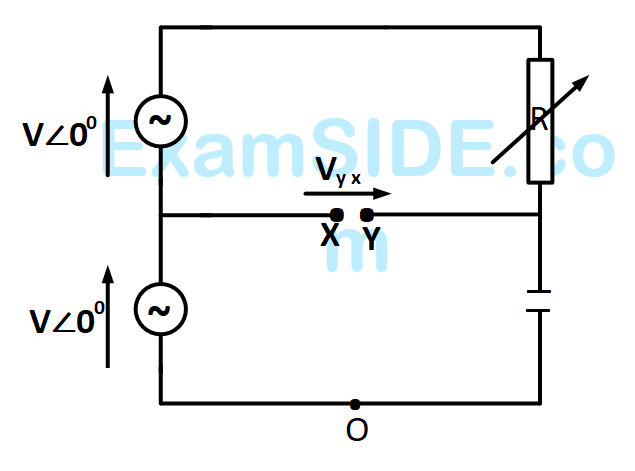
then the magnitude of $$R$$ is
23
The resonant frequency for the given circuit will be GATE EE 2007 Electric Circuits - Sinusoidal Steady State Analysis Question 9 English
24
In the figure given below, all phasors are with reference to the potential at point $$''O''.$$ The locus of voltage phasor $${V_{YX}}$$ as $$R$$ is varied from zero to infinity is shown by GATE EE 2007 Electric Circuits - Sinusoidal Steady State Analysis Question 10 English
25
The $$R-L-C$$ series circuit shown is supplied from a variable frequency voltage source. The admittance $$-$$ locus of the $$R-L$$ $$-C$$ network at terminals $$AB$$ for increasing frequency $$\omega $$ is GATE EE 2007 Electric Circuits - Sinusoidal Steady State Analysis Question 11 English
26
In the circuit shown in Fig. switch $$S{w_1}$$ is initially CLOSED and $$S{w_2}$$ is OPEN. The inductor $$L$$ carries a current of $$10$$ $$A$$ and the capacitor is charged to $$10$$ $$V$$ with polarities as indicated. $$S{w_2}$$ in initially CLOSED at $$t = {0^ - }$$ and $$S{w_1}$$ is OPENED at $$t=0.$$ The current through $$C$$ and the voltage across $$L$$ at $$t = {0^ + }$$ is GATE EE 2007 Electric Circuits - Transient Response Question 10 English
27
In the figure, transformer $${T_1}$$ has two secondaries, all three windings having the same number of turns and with polarities having the same number of turns and with polarities as indicated. One secondary is shorted by a $$10\,\Omega $$ resistor $$R,$$ and the other by a $$15\mu F$$ capacitor. The switch $$SW$$ is opened $$(t=0)$$ when the capacitor is charged to $$5$$ $$V$$ with the left plate as positive. At $$t=0+$$ the voltage $${V_P}$$ and current $${I_R}$$ are GATE EE 2007 Electric Circuits - Transient Response Question 12 English
28
A $$3$$ $$V$$ $$dc$$ supply with an internal resistance of $$2\,\,\Omega $$ supplies a passive non-linear resistance characterized by the relation $${V_{NL}} = {\rm I}_{NL}^2.$$ The power dissipated in the non-linear resistance is
29
The probes of a non $$-$$ isolated, two-channel oscilloscope are clipped to points $$A, B, $$ and $$C$$ in the circuit of the adjacent fig. $${V_{in}}$$ is a square wave of a suitable low frequency. The display on $$c{h_1}$$ and $$c{h_2}$$ are as shown on the right. Then the ''signal'' and ''Ground'' probes $${S_1},\,\,{G_1}$$ and $${S_2},\,\,{G_2}$$ of $$c{h_1}$$ and $$c{h_2}$$ respectively are connected to points. GATE EE 2007 Electrical and Electronics Measurement - Cathode Ray Oscilloscope Question 3 English
30
A three phase squirrel cage induction motor has a starting current of seven times the full load current and full load slip of $$5\% $$

If a starting torque of $$0.5$$ per unit is required then the per unit starting current should be

31
A $$100$$ $$kVA$$, $$415V,$$ star connected synchronous machine generates rated open circuit voltage $$415V$$ at a field current of $$15A.$$ The short circuit armature current at a field current of $$10A$$ is equal to the rated armature current. The per unit saturated synchronous reactance is
32
A $$3$$ phase, $$3$$ stack, variable reluctance stepper motor has $$20$$ poles on each rotor and stator stack. The step angle of this stepper motor is
33
A three phase synchronous motor connected to ac mains is running at full load and unity power factor. If its shaft load is reduced by half, with field current held constant, its new power factor will be
34
A three phase squirrel cage induction motor has a starting current of seven times the full load current and full load slip of $$5\% $$

If a star-delta starter is used to start this induction motor, the per unit staring torque will be

35
A three phase squirrel cage induction motor has a starting current of seven times the full load current and full load slip of $$5\% $$

If an auto-transformer is used for reduced voltage starting to provide $$1.5$$ per unit starting torque, the auto-transformer ratio $$\left( \% \right)$$ should be

36
A three-phase squirrel cage induction motor has a starting torque of $$150\% $$ and a maximum torque of $$300\% $$ with respect to rated torque at rated voltage and rated frequency. Neglect the stator resistance and rotational losses. The value of slip for maximum torque is
37
A single-phase $$50$$ $$kVA,$$ $$250$$ $$V/500V$$ two winding transformer has an efficiency of $$95\% $$ at full load, unity power factor. If it is reconfigured as a $$500V/750V$$ auto-transformer, its efficiency at its new rated load at unity power factor will be
38
In a transformer, zero voltage regulation at full load is
39
The dc motor, which can provide zero speed regulation at full load without any controller is
40
An inductor designed with $$400$$ turns coil wound on an iron core of $$16\,\,c{m^2}$$ cross sectional area and with a cut of an air gap length of $$1$$ $$mm$$. The coil is connected to a $$230$$ $$V,$$ $$50$$ $$Hz$$ ac supply. Neglect coil resistance, core loss, iron reluctance and leakage inductance. $$\left( {{\mu _0} = 4\pi \times {{10}^{ - 7}}\,H/m} \right)$$

The average force on the core to reduce the air gap will be

41
An inductor designed with $$400$$ turns coil wound on an iron core of $$16\,\,c{m^2}$$ cross sectional area and with a cut of an air gap length of $$1$$ $$mm$$. The coil is connected to a $$230$$ $$V,$$ $$50$$ $$Hz$$ ac supply. Neglect coil resistance, core loss, iron reluctance and leakage inductance. $$\left( {{\mu _0} = 4\pi \times {{10}^{ - 7}}\,H/m} \right)$$

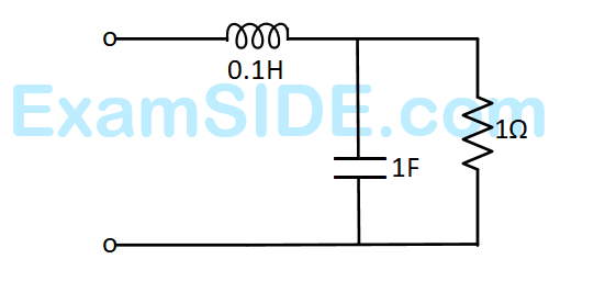
The current in the inductor is

42
A solid sphere made of insulating material has a radius $$R$$ and has a total charge $$Q$$ distributed uniformly in its volume. What is the magnitude of the electric field intensity, $$E,$$ at distribution $$r\left( {0 < r < R} \right)$$ inside the sphere?
43
Divergence of the vector field $$$\overrightarrow V\left(x,y,z\right)=-\left(x\cos xy\;+\;y\right)\;\widehat i\;+\;\left(y\cos xy\right)\;\widehat j\;+\;\left(\sin\;z^2\;+\;x^2\;+\;y^2\right)\widehat k$$$ is
44
Divergence of the vector field $$v\left( {x,y,z} \right) = - \left( {x\,\cos xy + y} \right)\widehat i + \left( {y\,\cos xy} \right)\widehat j + \left[ {\left( {\sin {z^2}} \right) + {x^2} + {y^2}} \right]\widehat k\,\,$$
45
Consider the function $$f\left( x \right) = {\left( {{x^2} - 4} \right)^2}$$ where $$x$$ is a real number. Then the function has
46
The integral $$\,\,{1 \over {2\pi }}\int\limits_0^{2\Pi } {Sin\left( {t - \tau } \right)\cos \tau \,d\tau \,\,\,} $$ equals
47
Let $$x$$ and $$y$$ be two vectors in a $$3-$$ dimensional space and $$ < x,y > $$ denote their dot product. Then the determinant det $$\left[ {\matrix{ { < x,x > } & { < x,y > } \cr { < y,x > } & { < y,y > } \cr } } \right] = $$ ______.
48
If $$A = \left[ {\matrix{ { - 3} & 2 \cr { - 1} & 0 \cr } } \right]$$ then $$A$$ satisfies the relation
49
If $$A = \left[ {\matrix{ { - 3} & 2 \cr { - 1} & 0 \cr } } \right]\,$$ then $${A^9}$$ equals
50
$$X = {\left[ {\matrix{ {{x_1}} & {{x_2}} & {.......\,{x_n}} \cr } } \right]^T}$$ is an $$n$$-tuple non-
zero vector. The $$n\,\, \times \,\,n$$ matrix $$V = X{X^T}$$
51
$${q_1},\,{q_2},{q_3},.......{q_m}$$ are $$n$$-dimensional vectors with $$m < n.$$ This set of vectors is linearly dependent. $$Q$$ is the matrix with $${q_1},\,{q_2},{q_3},.......{q_m}$$ as the columns. The rank of $$Q$$ is
52
In the circuit of adjacent figure the diode connects the $$ac$$ source to pure inductance $$L.$$ GATE EE 2007 Power Electronics - Single and Three Phase Rectifier Question 15 English

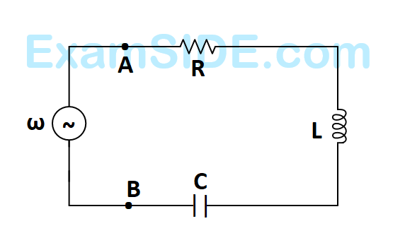
The diode conducts for

53
A single - phase inverter is operated in $$PWM$$ mode generating a single - pulse of width $$2d$$ in the center of each half cycle as shown in figure. It is found that the output voltage is free from $${5^{th}}$$ harmonic for pulse width $${144^0}.$$ What will be percentage of $${3^{rd}}$$ harmonic present in the output voltage $$\,\left( {{V_{03}}/{V_{01\,\,\,\max }}} \right)?$$ GATE EE 2007 Power Electronics - Inverters Question 17 English
54
A single - phase voltage source inverter is controlled in a single pulse - width modulated mode with a pulse width of $${150^0}$$ in each half cycle. Total harmonic distortion is defined as
$$THD = {{\sqrt {V_{rms}^2 - V_1^2} } \over {{V_1}}} \times 100,\,\,\,$$ Where $${{V_1}}$$ is the $$rms$$ value of the fundamental component of the voltage. The $$THD$$ of output $$ac$$ voltage waveform is
55
''Six $$MOSFETS$$ connected in a bridge configuration (having no other power device) MUST be operated as Voltage Source Inverter $$(VSI)''.$$ This statement is
56
A three - phase fully - controlled thyristor bridge converter is used as line commuted inverter to feed $$50kW$$ power $$420$$ $$V$$ $$dc$$ to a three phase, $$415$$ $$V$$ (line), $$50$$ $$Hz$$ $$ac$$ mains, Consider $$dc$$ link current to be constant. The $$rms$$ current of the thyristor is
57
The circuit in the figure is current commutated $$dc$$ $$-$$ $$dc$$ chopper where, $$T{h_M}$$ is the main $$SCR$$ and $$T{h_AUX}$$ is the auxiliary $$SCR$$. The load current is constant at $$10$$ $$A.$$
$$T{h_M}$$ is $$ON$$
$$T{h_AUX}$$ is trigged at $$t=0.$$ $$T{h_M}$$ is turned $$OFF$$ between. GATE EE 2007 Power Electronics - Choppers and Commutation Techniques Question 11 English
58
A $$1:1$$ pulse transformer $$(PT)$$ is used to trigger the $$SCR$$ in the adjacent figure. The $$SCR$$ is rated at $$1.5$$ $$kV$$, $$250$$ $$A$$ with $${{\rm I}_L} = 250\,mA,\,\,{{\rm I}_H} = 150\,mA,$$ and $${{\rm I}_{G\max }} = 150mA$$ with $${{\rm I}_L} = 250\,mA,$$ $${{\rm I}_{G\min }} = 100mA.$$ The $$SCR$$ is connected to an inductive load, where $$L$$ $$=150$$ $$mH$$ in series with a small resistance and the supply voltage is $$200$$ $$V$$ $$dc.$$ The forward drops of all transistors/diodes and gate $$-$$ cathode junction during $$ON$$ state are $$1.0V$$

The minimum approximate volt $$-$$second rating of the pulse transformer suitable for triggering the $$SCR$$ should be: (Volt - second rating is the maximum of product of the voltage and the width of the pulse that may be applied)

59
A $$1:1$$ pulse transformer $$(PT)$$ is used to trigger the $$SCR$$ in the adjacent figure. The $$SCR$$ is rated at $$1.5$$ $$kV$$, $$250$$ $$A$$ with $${{\rm I}_L} = 250\,mA,\,\,{{\rm I}_H} = 150\,mA,$$ and $${{\rm I}_{G\max }} = 150mA$$ with $${{\rm I}_L} = 250\,mA,$$ $${{\rm I}_{G\min }} = 100mA.$$ The $$SCR$$ is connected to an inductive load, where $$L$$ $$=150$$ $$mH$$ in series with a small resistance and the supply voltage is $$200$$ $$V$$ $$dc.$$ The forward drops of all transistors/diodes and gate $$-$$ cathode junction during $$ON$$ state are $$1.0V$$

The resistance $$R$$ should be

GATE EE 2007 Power Electronics - Power Semiconductor Devices Question 7 English
60
A single $$-$$ phase, $$230$$ $$V$$, $$50$$ $$Hz$$ $$ac$$ mains fed step down transformer $$(4:1)$$ is supplying power to a half $$-$$ wave uncontrolled $$ac$$ $$-$$ $$dc$$ converter used for charging a battery ($$12$$ $$V$$ $$dc$$) with the series current limiting resistor being $$19.04\,\Omega $$. The charging current is
61
A single phase full $$-$$ wave half $$-$$ controlled bridge converter feeds an inductive load. The two $$SCR's$$ in the converter are connected to a common $$DC$$ bus. The converter has to have a free wheeling diode
62
A single $$-$$ phase fully controlled thyristor bridge $$ac$$ $$-$$ $$dc$$ converter is operating at a firing angle of $${25^ \circ }$$ and an overlap angle of $${10^ \circ }$$ constant $$dc$$ output current of $$20$$ $$A$$. The fundamental power factor (displacement factor) at input $$ac$$ mains is
63
$$230$$ $$V$$ (phase) $$50$$ Hz, three-phase, $$4$$-wire, system has a sequence $$ABC$$. A unity power-factor load of $$4$$ kW is connected between phase A and neutral $$N$$. It is desired to achieve zero neutral current through the use of a pure inductor and pure capacitor in the other two phases. The Value of inductor and capacitor is......
64
Two regional system, each having several synchronous generators and loads are interconnected by an ac line and a HVDC link as shown in the figure. Which of the following statements is true in the steady state: GATE EE 2007 Power System Analysis - High Voltage Dc Transmission Question 3 English
65
Consider the protection system shown in the figure below. The circuit breakers numbered from $$1$$ to $$7$$ are of identical type. A single line to ground fault with zero fault impedance occurs at the midpoint of the line (at point F), but circuit breaker $$4$$ fails to operate (''Stuck breaker''). If the relays are coordinated correctly, a valid sequence of circuit breaker operation is GATE EE 2007 Power System Analysis - Circuit Breaker Question 3 English b
66
Suppose we define a sequence transformation between ''a-b-c'' and ''p-n-0''' variables as follows:
$$\left[ {\matrix{ {{f_a}} \cr {{f_b}} \cr {{f_c}} \cr } } \right] = k\left[ {\matrix{ 1 & 1 & 1 \cr {{\alpha ^2}} & \alpha & 1 \cr \alpha & {{\alpha ^2}} & 1 \cr } } \right]\left[ {\matrix{ {{f_p}} \cr {{f_n}} \cr {{f_o}} \cr } } \right]$$ where $$\,\alpha = {e^{j{{2\pi } \over 3}}}\,\,$$ and $$k$$ is a constant
Now, if it is given that:
$$\left[ {\matrix{ {{V_p}} \cr {{V_n}} \cr {{V_o}} \cr } } \right] = k\left[ {\matrix{ {0.5} & 0 & 0 \cr 0 & {0.5} & 0 \cr 0 & 0 & {2.0} \cr } } \right]\left[ {\matrix{ {{i_p}} \cr {{I_n}} \cr {{i_o}} \cr } } \right]\,\,$$ and $$\left[ {\matrix{ {{V_a}} \cr {{V_b}} \cr {{V_c}} \cr } } \right] = z\left[ {\matrix{ {{i_a}} \cr {{I_b}} \cr {{i_c}} \cr } } \right]\,\,$$ then,
67
Consider a synchronous generator connected to an infinite bus by two identical parallel transmission lines. The transient reactance $$x'$$ of the generator $$0.1$$ pu. Due to some previous disturbance, the rotor angle $$(d)$$ is undergoing an undamped oscillation, with the maximum value of $$\delta \left( t \right)$$ equal to $$\,{130^ \circ }\,.$$ One of the parallel lines trip due to relay mal-operation at an instant $$\,\,\,\,\,$$ when $$\,\delta \left( t \right)\,\, = {130^ \circ }\,\,$$ as shown in the figure. The maximum value of the per unit line reactance $$x,$$ such that the system does not lose synchronism subsequent to this tripping is GATE EE 2007 Power System Analysis - Power System Stability Question 19 English
68
The incremental cost curves in Rs/MWhr for two generators supplying a common load of $$700$$ MW are shown in the figures. The maximum and minimum generation limits are also indicated. The optimum generation schedule is: GATE EE 2007 Power System Analysis - Power Generation Cost Question 17 English
69
Consider a bundled conductor of an overhead line consisting of three identical sub-conductors placed at the corners of an equilateral triangle as shown in figure. If we neglect the charges on the other phase conductors and ground, and assume that spacing between sub-conductors is much larger than their radius, the maximum electric field intensity is experienced at GATE EE 2007 Power System Analysis - Parameters and Performance of Transmission Lines Question 5 English
70
Consider the transformer connections in a part of a power system shown in the figure. The nature of transformer connections and phase shifts are indicated for all but one transformer. Which of the following connections, and the corresponding phase shift $$\theta ,$$ should be used for the transformer between $$A$$ and $$B$$? GATE EE 2007 Power System Analysis - Parameters and Performance of Transmission Lines Question 6 English
71
Single line diagram of a $$4$$-bus single source distribution system is shown below. Branches $${e_1},\,\,$$ $${e_2},\,\,$$ $${e_3}\,\,$$ and $${e_4}\,\,$$ have equal impedences. The load current values indicated in the figure are in per unit. GATE EE 2007 Power System Analysis - Parameters and Performance of Transmission Lines Question 7 English

Distribution Company's policy requires radial system operation with minimum loss. This can be achieved by opening of the branch

72
The total reactance and total susceptance of a lossless overhead $$EHV$$ line, operating at $$50$$ $$Hz,$$ are given by $$0.045$$ pu and $$1.2$$ pu respectively. If the velocity of wave propagation is $$3\,\, \times \,\,{10^5}$$ km/s, then the approximate length of line is
73
Let a signal $${a_1}\,\sin \left( {{\omega _1}t + {\phi _1}} \right)$$ be applied to a stable linear time-invariant system. Let the corresponding steady state output be represented as $${a_2}F\left( {{\omega _2}t + {\phi _2}} \right).$$ Then which of the following statements is true?
74
The frequency spectrum of a signal is shown in the figure. If this is ideally sampled at intervals of $$1$$ $$ms,$$ then the frequency spectrum of the sampled signal will be GATE EE 2007 Signals and Systems - Sampling Theorem Question 2 English
75
A signal $$x(t)$$ is given by
$$x\left( t \right) = \left\{ {\matrix{ {1, - {\raise0.5ex\hbox{$\scriptstyle T$} \kern-0.1em/\kern-0.15em \lower0.25ex\hbox{$\scriptstyle 4$}} < t \le {\raise0.5ex\hbox{$\scriptstyle {3T}$} \kern-0.1em/\kern-0.15em \lower0.25ex\hbox{$\scriptstyle 4$}}} \cr { - 1,{\raise0.5ex\hbox{$\scriptstyle {3T}$} \kern-0.1em/\kern-0.15em \lower0.25ex\hbox{$\scriptstyle 4$}} < t \le {\raise0.5ex\hbox{$\scriptstyle {7T}$} \kern-0.1em/\kern-0.15em \lower0.25ex\hbox{$\scriptstyle 4$}},\,\,\,} \cr { - x\left( {t + T} \right)} \cr } } \right.$$ Which among the following gives the fundamental Fourier term of $$x(t)$$?
76
A signal is processed by a causal filter with transfer function $$G(s).$$ For a distortion free output signal waveform, $$G(s)$$ must.

$$G\left( z \right) = a{z^{ - 1}} + \beta \,\,{z^{ - 3}}$$ is a low-pass digital filter with a phase characteristic same as that of the above question if

77
Consider the discrete-time system shown in the figure where the impulse response of $$G\left( z \right)$$ is
$$g\left( 0 \right) = 0,\,\,g\left( 1 \right) = g\left( 2 \right) = 1,\,g\left( 3 \right) = g\left( 4 \right) = .... = 0$$ GATE EE 2007 Signals and Systems - Linear Time Invariant Systems Question 10 English

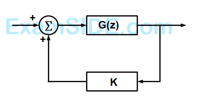
This system is stable for range of values of $$K$$

78
A signal is processed by a causal filter with transfer function $$G(s).$$ For a distortion free output signal waveform, $$G(s)$$ must
79
$$X\left( z \right) = 1 - 3\,\,{z^{ - 1}},\,\,Y\left( z \right) = 1 + 2\,\,{z^{ - 2}}$$ are $$Z$$-transforms of two signals $$x\left[ n \right],\,\,y\left[ n \right]$$ respectively. A linear time invariant system has the impulse response $$h\left[ n \right]$$ defined by these two signals as $$h\left[ n \right] = x\left[ {n - 1} \right] * y\left[ n \right]$$ where $$ * $$ denotes discrete time convolution. Then the output of the system for the input $$\delta \left[ {n - 1} \right]$$
80
If u(t), r(t) denote the unit step and unit ramp functions respectively and u(t)*r(t) their convolution, then the function u(t+1)*r(t-2) is given by
EXAM MAP
Medical
NEETAIIMS
Graduate Aptitude Test in Engineering
GATE CSEGATE ECEGATE EEGATE MEGATE CEGATE PIGATE IN
Civil Services
UPSC Civil Service
Defence
NDA
Staff Selection Commission
SSC CGL Tier I
CBSE
Class 12