GATE EE 2010
View Questions

GATE EE

Assuming that the diodes an ideal in the given circuit, the voltage $${V_0}$$ is
View Question
The transistor circuit shown uses a silicon transistor with $${V_{BE}} = 0.7V,{{\rm I}_C} \approx {{\rm I}_E}$$ and a $$
View Question
Given that the op-amp is ideal, the $$O/P$$ voltage $${V_0}$$ is
View Question
As shown in the figure, a negative feedback system has an amplifier of gain $$100$$ with $$ \pm 10\% $$ tolerance in the
View Question
For the system $${2 \over {\left( {s + 1} \right)}},$$ the approximate time taken for a step response to reach $$98$$% o
View Question
The characteristic equation of a closed-loop system is $$s\left( {s + 1} \right)\left( {s + 3} \right) + \,\,k\left( {s
View Question
The frequency response of $$G\left( s \right) = 1/\left[ {s\left( {s + 1} \right)\left( {s + 2} \right)} \right]$$ plott
View Question
The system $$\mathop X\limits^ \bullet = AX + BU$$ with $$A = \left[ {\matrix{ { - 1} & 2 \cr 0 & 2
View Question
A minimized form of the function $$F$$ is
View Question
Which of the following circuits is a realization of the previous function $$F$$ $$?$$
View Question
The $$TTL$$ circuit shown in the figure is fed with the waveform $$X$$ (also shown). All gates have equal propagation de
View Question
When a $$''CALL$$ $$addr'$$ instruction is executed, the $$CPU$$ carries out the following sequential operations interna
View Question
If the electrical circuit of figure (b) is an equivalent of the coupled tank system of figure (a), then
View Question
As shown in the figure, a 1 Ω resistance is connected across a source that has a load line v + i = 100. The current thro
View Question
If the 12 Ω resistor draws a current of 1A as shown in the figure, the value of resistance R is
View Question
The switch in the circuit has been closed for a long time. It is opened at t = 0. At t = 0+, the current through the 1μF
View Question
The two-port network P shown in the figure has ports 1 and 2, denoted by terminals (a, b) and (c, d), respectively. It h
View Question
An ammeter has a current range of $$0$$-$$5A,$$ and its internal resistance is $$0.2\Omega $$. In order to change the ra
View Question
The Maxwell's bridge shown in the fig. is at balance, the parameters of the inductive coil are
View Question
A wattmeter is connected as shown in the fig. the wattmeter reads
View Question
A separately excited DC motor runs at 1500 rpm under no-load with 200 V applied to the armature. The field voltage is ma
View Question
A separately excited DC motor runs at 1500 rpm under no-load with 200 V applied to the armature. The field voltage is ma
View Question
A single-phase transformer has a turns ratio of 1:2, and is connected to a purely resistive load as shown in the figure.
View Question
A balanced star-connected and purely resistive load is connected at the secondary of a star-delta transformer as shown i
View Question
A balanced three-phase voltage is applied to a star-connected induction motor, the phase to neutral voltage being V. The
View Question
A separately excited $$dc$$ machine is coupled to a $$50Hz,$$ three-phase, 4-pole induction machine as shown in the figu
View Question
A $$50$$ $$Hz$$ synchronous generator is initially connected to a long lossless transmission line which is open circuite
View Question
Divergence of the three-dimentional radial vector field $$\overrightarrow F$$ is
View Question
For the set of equations $$${x_1} + 2{x_2} + {x_3} + 4{x_4} = 2,$$$ $$$3{x_1} + 6{x_2} + 3{x_3} + 12{x_4} = 6.$$$ The f
View Question
An eigen vector of $$p = \left[ {\matrix{ 1 & 1 & 0 \cr 0 & 2 & 2 \cr 0 & 0 & 3 \c
View Question
The value of the quantity, where $$P = \int\limits_0^1 {x{e^x}\,dx\,\,\,} $$ is
View Question
At $$t=0,$$ the function $$f\left( t \right) = {{\sin t} \over t}\,\,$$ has
View Question
Divergence of the $$3$$ $$-$$ dimensional radial vector field $$\overrightarrow r $$ is
View Question
A box contains $$4$$ white balls and $$3$$ red balls. In succession, two balls are randomly selected and removed from th
View Question
For the differential equation $${{{d^2}x} \over {d{t^2}}} + 6{{dx} \over {dt}} + 8x = 0$$ with initial conditions $$x(
View Question
Given $$f\left( t \right) = {L^{ - 1}}\left[ {{{3s + 1} \over {{s^3} + 4{s^2} + \left( {k - 3} \right)}}} \right].$$ $$
View Question
Figure shows a composite switch consisting of a power transistor $$(BJT)$$ in series with a diode. Assuming that the tra
View Question
The fully controlled thyristor converter in the figure is fed from a single-phase source. When the firing angle is $${0^
View Question
The power electronic converter shown in the figure has a single-pole double-throw switch. The pole $$P$$ of the switch i
View Question
The L-C circuit shown in the figure has an inductance $$L=1mH$$ and a capacitance $$C = 10\mu F.$$ The initial current t
View Question
The L-C circuit shown in the figure has an inductance $$L=1mH$$ and a capacitance $$C = 10\mu F.$$ The $$L$$-$$C$$ circu
View Question
Consider two buses connected by an impedance of $$\left( {0 + j5} \right)\Omega .$$ The bus $$1$$ voltage is $$100$$$$\a
View Question
Consider a step voltage wave of magnitude $$1$$ pu travelling along a loss less transmission line that terminates in a r
View Question
Consider a three-core, three phase, $$50$$ $$Hz$$, $$11$$ $$kV$$ cable whose conductors are denoted as $$R, Y$$ and $$B$
View Question
A $$50$$ $$Hz$$ synchronous generator is initially connected to a long lossless transmission line which is open circuite
View Question
Consider a three-phase, $$50Hz,$$ $$11$$ $$kV$$ distribution system. Each of the conductors is suspended by an insulator
View Question
The zero-sequence circuit of the three phase transformer shown in the figure is
View Question
A three-phase, $$33$$ kV oil circuit breaker is rated $$1200$$ A, $$2000$$ MVA, $$3$$s. The symmetrical breaking current
View Question
Consider a stator winding of an alternator with an internal high resistance ground fault. The currents under the fault c
View Question
Power is transferred from system $$A$$ to system $$B$$ by an $$HVDC$$ link as shown in the figure. If the voltage $${V_{
View Question
For the power system shown in the figure below, the specifications of the components are the following: $$G1: 25$$ $$kV,
View Question
For the system $$\frac2{\left(s+1\right)}$$, the approximate time taken for a step response to reach 98% of its final va
View Question
Given the finite length input x[n] and the corresponding finite length output y[n] of an LTI system as shown below, the
View Question
The system represented by the input-output relationship $$y\left(t\right)=\int_{-\infty}^{5t}x\left(\tau\right)d\tau$$,
View Question
The period of the signal $$x\left(t\right)=8\sin\left(0.8\mathrm{πt}+\frac{\mathrm\pi}4\right)$$ is
View Question
The second harmonic component of the periodic waveform given in the figure has an amplitude of
View Question
x(t) is a positive rectangular pulse from t = -1 to t = +1 with unit height as shown in the figure. The value of $$\int_
View Question
Given f(t) and g(t)as shown below: 
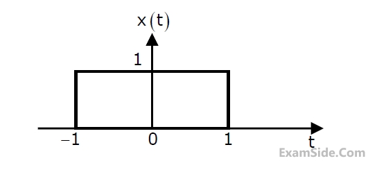
The Laplace transform of g(t) is
View Question
Given f(t) and g(t)as shown below: g(t) can be expressed as
View Question
EXAM MAP
Medical
NEET
Graduate Aptitude Test in Engineering
GATE CSEGATE ECEGATE EEGATE MEGATE CEGATE PIGATE IN
CBSE
Class 12