GATE EE 2008
View Questions

GATE EE

1
The truth of a monoshot shown in the figure is given in the table below: GATE EE 2008 Analog Electronics - 555 Timer Question 1 English 1

Two monoshots, one positive edge triggered and other negative edge triggered, are connected as shown in the figure. The pulse widths of the two monoshot options, $${Q_1}$$ and $${Q_2}$$ are $${T_{O{N_1}}}$$ and $${T_{O{N_2}}}$$ respectively.

GATE EE 2008 Analog Electronics - 555 Timer Question 1 English 2

The frequency and the duty cycle of the signal at $${Q_1}$$ will respectively be

GATE EE 2008 Analog Electronics - 555 Timer Question 1 English 3
2
A waveform generator circuit using $$OPAMPs$$ is shown in the figure. It produces a triangular wave at point $$'P'$$ with a peak to peak voltage of $$5V$$ for $${v_1} = 0\,V.$$ GATE EE 2008 Analog Electronics - Operational Amplifier Question 8 English

If the voltage $${v_1}$$ is made $$+2.5$$ $$V,$$ the voltage waveform at $$'P'$$ will become.

3
A general filter circuit is shown in figure GATE EE 2008 Analog Electronics - Operational Amplifier Question 25 English 1

The output of the filter in above is given to the circuit shown in figure The gain $${V_S}$$ frequency characteristic of the $$0/p$$ $$\left( {{V_0}} \right)$$ will be

GATE EE 2008 Analog Electronics - Operational Amplifier Question 25 English 2
4
A general filter circuit is shown in figure GATE EE 2008 Analog Electronics - Operational Amplifier Question 26 English

If $${R_1} = {R_2} = {R_A}$$ and $${R_3} = {R_4} = {R_B},$$ the circuit acts as a

5
The block diagram of two types of half wave rectifiers are shown in figure. The transfer characteristics of the rectifiers are also shown within the block GATE EE 2008 Analog Electronics - Operational Amplifier Question 27 English

It is desired to make full wave rectifier using two half wave rectifiers. The resultant circuit will be

6
Two perfectly matched silicon transistors are connected as shown in the figure. Assuming the $$\beta $$ of the transistors to be very high and forward voltage drop to be $$0.7V,$$ the value of current $${\rm I}$$ is (assume diode $$(D)$$ is ideal) GATE EE 2008 Analog Electronics - Bjt and Mosfet Biasing Question 2 English
7
In the voltage doubler circuit shown in figure, the switch $$' S '$$ is closed at $$t=0$$. Assuming diodes $${D_1}$$ & $${D_2}$$ to be ideal, load resistance to be infinite and initial capacitor voltages to be zero, the steady state voltage across capacitors $${C_1}$$ & $${C_2}$$ will be GATE EE 2008 Analog Electronics - Diode Circuits and Applications Question 6 English
8
The equivalent circuits of a diode, during forward and reverse biased conditions are shown in figure.
(a) GATE EE 2008 Analog Electronics - Diode Circuits and Applications Question 12 English 1
(b) GATE EE 2008 Analog Electronics - Diode Circuits and Applications Question 12 English 2

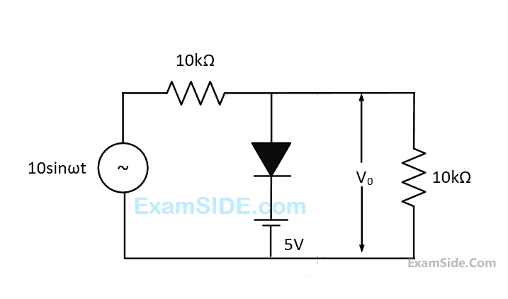
If such diodes are used in the clipper circuit of figure given above, the output voltage (V0) of the circuit will be

9
The transfer function of a linear time invariant system is given as $$G\left( s \right) = {1 \over {{s^2} + 3s + 2}}$$

The steady state value of the output of the system for a unit impulse input applied at time instant $$t=1$$ will be

10
The state space equation of a system is described by $$\mathop X\limits^ \bullet = AX + BU,\,\,Y = Cx$$ where $$X$$ is state vector, $$U$$ is input, $$Y$$ is output and $$$A = \left( {\matrix{ 0 & 1 \cr 0 & { - 2} \cr } } \right)\,\,B = \left( {\matrix{ 0 \cr 1 \cr } } \right)\,\,C = \left[ {\matrix{ 1 & 0 \cr } } \right]$$$

A unity feedback is provided to the above system $$G(s)$$ to make it a closed loop system as shown in figure.

GATE EE 2008 Control Systems - State Variable Analysis Question 20 English

For a unit step input $$r(t),$$ the steady state error in the input will be

11
The state space equation of a system is described by $$\mathop X\limits^ \bullet = AX + BU,\,\,Y = Cx$$ where $$X$$ is state vector, $$U$$ is input, $$Y$$ is output and $$$A = \left( {\matrix{ 0 & 1 \cr 0 & { - 2} \cr } } \right)\,\,B = \left( {\matrix{ 0 \cr 1 \cr } } \right)\,\,C = \left[ {\matrix{ 1 & 0 \cr } } \right]$$$

The transfer function $$G(s)$$ of this system will be

12
The transfer function of two compensators are given below: $${C_1} = {{10\left( {s + 1} \right)} \over {\left( {s + 10} \right)}},\,{C_2} = {{s + 10} \over {10\left( {s + 1} \right)}}$$

Which one of the following statements is correct?

13
The asymptotic Bode magnitude plot of a minimum phase transfer function is shown in the figure: GATE EE 2008 Control Systems - Polar Nyquist and Bode Plot Question 10 English

This transfer function has

14
Figure shows a feedback system where $$K>0$$ GATE EE 2008 Control Systems - Routh Hurwitz Stability Question 5 English

The range of $$k$$ for which system is stable will by given by

15
The transfer function of a system is given as $${{100} \over {{s^2} + 20s + 100}}.$$ The system is
16
A function $$y(t)$$ satisfies the following differential equation : $${{dy\left( t \right)} \over {dt}} + y\left( t \right) = \delta \left( t \right)$$

Where $$\delta \left( t \right)$$ is the delta function. Assuming zero initial condition, and denoting the unit step function by $$u(t),y(t)$$ can be of the form

17
A $$3$$ line to $$8$$ line decoder, with active low outputs, is used to implement a $$3$$- variable Boolean function as shown in the figure: The simplified form of Boolean function $$F(X,Y,Z)$$ implemented in 'Product of Sum' form will be GATE EE 2008 Digital Electronics - Combinational Circuits Question 2 English
18
An input device is interfaced with Intel $$8085$$ $$A$$ microprocessor as memory mapped $${\rm I}/O,$$ the address of the device is $$2500H.$$ In order to input data from the device to accumulator, the sequence of instructions will be
19
The contents (in Hexadecimal) of some of the memory locations in an $$8085A$$ based system are given below GATE EE 2008 Digital Electronics - Microprocessor Question 9 English

The contents of stack pointer $$(SP),$$ program counter $$(PC)$$ and $$(HL)$$ are $$270H,$$ $$2100H$$ and $$0000H$$ respectively. When the following sequence of instructions are executed,
$$2100H:$$ $$DAD$$ $$SP$$
$$2101H;$$ $$PCHL$$

The contents of $$(SP)$$ and $$(PC)$$ at the end of execution will be

20
The time constant for the given circuit will be GATE EE 2008 Electric Circuits - Transient Response Question 11 English
21
The number of chords in the graph of the given circuit will be GATE EE 2008 Electric Circuits - Graph Theory Question 4 English
22
In the circuit shown in the figure, the value of the current $$i$$ will be given by GATE EE 2008 Electric Circuits - Network Elements Question 8 English
23
Assuming ideal elements in the circuit shown below, the voltage $${V_{ab}}$$ will be GATE EE 2008 Electric Circuits - Network Elements Question 10 English
24
The Thevenin's equivalent of a circuit operating at $$\omega = 5\,\,rad/s\,\,{V_{oc}} = 3.71\angle - {15.9^ \circ }$$ and $${Z_0} = 2.38 - j0.667\Omega .$$ At this frequency, the minimal realization of the Thevenin's independence will have a
25
Two $$8$$ $$A$$ $$D$$ $$C$$ $$s$$ one of single slope integrating type and other of successive approximation type. Take $${T_A}$$ and $${T_B}$$ times to connect $$5V$$ analog input signal to equivalent digital output. If the input analog signal is reduced to $$2.5V$$ the approximate time taken by the two $$ADC's$$ will respectively be
26
Two Sinusoidal signal $$p\left( {{\omega _1}t} \right) = A\,\sin \omega t,$$ and $$q\left( {{\omega _2}t} \right)$$ are applied to $$X$$ and $$Y$$ inputs of a dual channel $$C.R.O,$$ the lissajous figure displayed on the screen is shown below. The signal $$q\left( {{\omega _2}t} \right)$$ will be represented as GATE EE 2008 Electrical and Electronics Measurement - Cathode Ray Oscilloscope Question 2 English
27
The ac bridge shown in the figure is used to measure the impedance $$Z.$$ If the bridge is balanced for oscillator frequency $$f=2$$ $$kHz$$, then the impedance $$Z$$ will be GATE EE 2008 Electrical and Electronics Measurement - Measurement of Resistance and A.C Bridges Question 2 English
28
A bridge circuit is shown in the figure below. Which one of the sequence given below is most suitable for balancing the bridge? GATE EE 2008 Electrical and Electronics Measurement - Measurement of Resistance and A.C Bridges Question 3 English
29
A $$230V,$$ $$50Hz,$$ $$4$$ pole, single phase induction motor is rotating in the clockwise (forward) direction at a speed of $$1425$$ $$rpm.$$ If the rotor resistance at standstill is $$7.8\,\,\Omega ,$$ then the effective rotor resistance in the backward branch of the equivalent circuit will be
30
A synchronous motor is connected to an infinite bus at $$1.0$$ $$p.u$$ voltage and draws $$0.6$$ $$pu$$ at unity power factor. Its synchronous reactance is $$1.0$$ $$pu$$ and resistance is negligible.

The excitation voltage and load angle will respectively be

31
A synchronous motor is connected to an infinite bus at $$1.0p.u$$ voltage and draws $$0.6$$ $$pu$$ at unity power factor. Its synchronous reactance is $$1.0$$ $$pu$$ and resistance is negligible.

Keeping the excitation voltage same, the load on the motor is increased such that the motor current increases by $$20\% $$. The operating power factor will become

32
Distributed winding and short chording employed in AC machines will result in
33
In a stepper motor, the detent torque means
34
A $$3$$-phase, $$440$$ $$V,$$ $$50$$ $$Hz,$$ $$4$$ pole, slip ring induction motor is feed from the rotor side through an auto transformer and the stator is connected to a variable resistance as shown in the figure. GATE EE 2008 Electrical Machines - Induction Machines Question 11 English

The motor is coupled to a $$220$$ $$V$$, separately excited $$d.c.$$ generator feeding power to fixed resistance of $$10\Omega .$$ Two watt-meter method is used to measure the input power to induction motor. The variable resistance is adjusted such that motor recorded
$${W_1} = 1800\,W,\,\,{W_2} = - 200\,W.$$

Neglecting all losses of both the machines, the $$dc$$ generator power output and the current through resistance $$\left( {{R_{ex}}} \right)$$ will respectively be

35
A $$3$$-phase, $$440$$ $$V,$$ $$50$$ $$Hz,$$ $$4$$ pole, slip ring induction motor is feed from the rotor side through an auto transformer and the stator is connected to a variable resistance as shown in the figure. GATE EE 2008 Electrical Machines - Induction Machines Question 12 English

The motor is coupled to a $$220$$ $$V$$, separately excited $$d.c.$$ generator feeding power to fixed resistance of $$10\Omega .$$ Two watt-meter method is used to measure the input power to induction motor. The variable resistance is adjusted such that motor recorded
$${W_1} = 1800\,W,\,\,{W_2} = - 200\,W.$$

The Speed of rotation of stator magnetic field with respect to rotor structure will be

36
A $$400$$ $$V,$$ $$50$$ $$Hz,$$ $$30$$ $$hp,$$ three-phase induction motor is drawing $$50$$ A current at $$0.8$$ power factor lagging. The stator and rotor copper losses are $$1.5kW$$ and $$900$$ $$W$$ respectively. The friction and windage losses are $$1050$$ $$W$$ and the core losses are $$1200$$ $$W.$$ The air-gap power of the motor will be
37
A $$400$$ $$V,$$ $$50$$ $$Hz$$, $$4$$ pole, $$1400$$ $$rpm$$, star connected squirrel cage induction motor has the following parameters referred to the stator:
$$R = 1.0\,\Omega ,{X_s} = X{'_r} = 1.5\,\Omega $$ Neglect stator resistance and core and rotational losses of the motor. The motor is controlled from a $$3$$-phase voltage source inverter with constant $$V/f$$ control. The stator line-to-line voltage $$(rms)$$ and frequency to obtain the maximum torque at starting will be:
38
The core of two-winding transformer is subjected to a magnetic flux variation as indicated in the figure. GATE EE 2008 Electrical Machines - Transformers Question 17 English 1 GATE EE 2008 Electrical Machines - Transformers Question 17 English 2

The induced $$emf$$ $$\left( {{e_{rs}}} \right)$$ in the secondary winding as a function of time will be of the form

39
Three single-phase transformers are connected to form a $$3$$-phase transformer bank. The transformers are connected in the following manner. GATE EE 2008 Electrical Machines - Transformers Question 20 English

The transformer connection will be represented by

40
It is desired to measure parameters of $$230$$ $$V/115$$ $$V,$$ $$2$$ $$kVA$$, single-phase transformers. The following watt-meters are available in a laboratory:
$${W_1}:250\,\,V,\,\,\,10\,\,A,\,\,\,\,\,\,$$ Low Power Factor
$${W_2}:250\,\,V,\,\,\,5\,\,A,\,\,\,\,\,\,$$ Low Power Factor
$${W_3}:150\,\,V,\,\,\,10\,\,A,\,\,\,\,\,\,$$ High Power Factor
$${W_4}:150\,\,V,\,\,\,5\,\,A,\,\,\,\,\,\,$$ High Power Factor

The watt-meters used in open circuit test and short circuit test of the transformer will respectively be

41
A $$240V$$ $$dc$$ shunt motor draws $$15A$$ while supplying the rated load at a speed of $$80$$ $$rad/s$$. The armature resistance is $$0.5$$ $$ohm$$ and the field winding resistance is $$80$$ $$ohm.$$

The net voltage across the armature resistance at the time of plugging will be

42
A $$240V$$ $$dc$$ shunt motor draws $$15A$$ while supplying the rated load at a speed of $$80$$ $$rad/s$$. The armature resistance is $$0.5$$ $$ohm$$ and the field winding resistance is $$80$$ $$ohm.$$

The external resistance to be added in the armature circuit to limit the armature current to $$125\% $$ of its rated value is

43
A capacitor consists of two metal plates each $$500 \times 500\,\,m{m^2}$$ and spaced $$6$$ $$mm$$ apart. The space between the metal plates is filled with a glass plate of $$4$$ $$mm$$ thickness and a layer of paper of $$2$$ $$mm$$ thickness. The relative permittivity of the glass and paper are $$8$$ and $$2$$ respectively. Neglecting the fringing effect, the capacitance will be (Given that $${\varepsilon _0} = 8.85 \times {10^{ - 12}}\,F/m$$ )
44
Two point charges $${Q_1} = 10\,\,\mu C$$ and $${Q_2} = 20\,\,\mu C$$ are placed at coordinates $$(1,1,0)$$ and $$\left( { - 1, - 1,0} \right)$$ respectively. The total electric flux passing through a plane $$z=20$$ will be
45
A coil of 300 turns is wound on a non-magnetic core having a mean circumference of 300 mm and a cross-sectional area of 300 mm2. The inductance the coil corresponding to a magnetizing current of 3 A will be ( Given that $$\mu_0=4\mathrm\pi\times10^{-7}\;\mathrm H/\mathrm m$$)
46
Equation $${e^x} - 1 = 0\,\,$$ is required to be solved using Newton's method with an initial guess $$\,\,{x_0} = - 1.\,\,$$ Then after one step of Newton's method estimate $${x_1}$$ of the solution will be given by
47
Given $$X(z) = {z \over {{{(z - a)}^2}}}$$ with |z| > a, the residue of $$X(z){z^{n - 1}}$$ at z = a for $$n \ge 0$$ will be
48
A differential equation $${{dx} \over {dt}} = {e^{ - 2t}}\,\,u\left( t \right)\,\,$$ has to be solved using trapezoidal rule of integration with a step size $$h=0.01$$ sec. Function $$u(t)$$ indicates a unit step function. If $$x(0)=0$$ then the value of $$x$$ at $$t=0.01$$ sec will be given by
49
$$X$$ is uniformly distributed random variable that take values between $$0$$ and $$1.$$ The value of $$E\left( {{X^3}} \right)$$ will be
50
Let $$P$$ be $$2x2$$ real orthogonal matrix and $$\overline x $$ is a real vector $${\left[ {\matrix{ {{x_1}} & {{x_2}} \cr } } \right]^T}$$ with length $$\left| {\left| {\overline x } \right|} \right| = {\left( {{x_1}^2 + {x_2}^2} \right)^{1/2}}.$$ Then which one of the following statement is correct?
51
$$A$$ is $$m$$ $$x$$ $$n$$ full rank matrix with $$m > n$$ and $${\rm I}$$ is an identity matrix. Let matrix $${A^ + } = {\left( {{A^T}A} \right)^{ - 1}}{A^T}.$$ Then which one of the following statement is false?
52
If the rank of a $$5x6$$ matrix $$Q$$ is $$4$$ then which one of the following statements is correct?
53
The characteristic equation of a $$3\,\, \times \,\,3$$ matrix $$P$$ is defined as
$$\alpha \left( \lambda \right) = \left| {\lambda {\rm I} - P} \right| = {\lambda ^3} + 2\lambda + {\lambda ^2} + 1 = 0.$$
If $${\rm I}$$ denotes identity matrix then the inverse of $$P$$ will be
54
In the single phase voltage controller circuit shown in the figure, for what range of triggering angle $$\left( \alpha \right)$$, the output voltage $$\left( {{V_0}} \right)$$ is not controllable? GATE EE 2008 Power Electronics - Ac Voltage Controllers Question 2 English
55
A single phase fully controlled converter bridge is used for electrical braking of a separately excited $$dc$$ motor. The $$dc$$ motor load is represented by an equivalent circuit as shown in the figure. GATE EE 2008 Power Electronics - Single and Three Phase Rectifier Question 13 English

Assume that the load inductance is sufficient to ensure continuous and ripple free load current. The firing angle of the bridge for a load current of $${{\rm I}_0} = 10\,\,A$$ will be

56
A single - phase half controlled converter shown in the figure feeding power to highly inductive load. The converter is operating at a firing angle of $${60^ \circ }.$$ GATE EE 2008 Power Electronics - Single and Three Phase Rectifier Question 14 English

If the firing pulses are suddenly removed, the steady state voltage $$\left( {{V_0}} \right)$$ waveform of the converter will become

57
A single phase voltage source inverter is feeding a purely inductive load as shown in the figure. GATE EE 2008 Power Electronics - Inverters Question 16 English

The inverter is operated at $$50$$ $$Hz$$ in $${180^0}$$ square wave mode. Assume that the load current does not have any $$dc$$ component. The peak value of the inductor current $${i_0}$$ will be

58
A $$3$$ - phase voltage source Inverter is operated in $${180^ \circ }$$ conduction mode. Which one of the following statements is true?
59
In the circuit shown in the figure, the switch is operated at a duty cycle of $$0.5.$$ A large capacitor current is connected across the load. The inductor current is assumed to be continuous. GATE EE 2008 Power Electronics - Choppers and Commutation Techniques Question 10 English

The average voltage across the load and the average current through the diode will respectively be

60
A single phase full bridge converter supplies a load drawing constant and ripple free load current. If the triggering angle is $${30^ \circ },$$ the input power factor will be
61
A three phase fully controlled bridge converter is feeding a load drawing a constant and ripple free load current of $$10$$ $$A$$ at a firing angle of $${30^ \circ }.$$ The approximate Total Harmonic Distortion $$(\% \,\,THD)$$ and $$r.m.s$$ value of fundamental component of the input current will respectively be
62
A lossless power system has to serve a load of $$250$$ $$MW.$$ There are two generators ($$G1$$ and $$G2$$) in the system with cost curves $${C_1}$$ and $${C_2}$$ respectively defined as follows:
$${C_1}\left( {{P_{G1}}} \right) = {P_{G1}} + 0.055 \times P_{G1}^2$$
$${C_2}\left( {{P_{G2}}} \right) = 3{P_{G2}} + 0.03 \times P_{G2}^2$$
Where $${P_{G1}}$$ and $${P_{G2}}$$ are the MW injections from generator $${G_1}$$ and $${G_2}$$ respectively. Thus, the minimum cost dispatch will be
63
Given that: $$\,{V_{s1}} = {V_{s2}} = 1 + j0\,\,p.u,\,\, + ve\,\,$$ sequence impedance are $$\,{Z_{s1}} = {Z_{s2}} = 0.001 + j0.01\,\,p.u\,\,$$ and $${Z_L} = 0.006 + j\,0.06\,\,p.u,\,\,3\phi .\,\,\,$$ Base $$MVA=100,$$ voltage base $$=400$$ $$kV(L-L).$$
Nominal system frequency $$= 50$$ $$Hz.$$ The reference voltage for phase $$'a'$$ is defined as $$\,\,V\left( t \right) = {V_m}\,\cos \left( {\omega t} \right).\,\,\,$$ A symmetrical $$3\phi $$ fault occurs at centre of the line, i.e., at point $$'F'$$ at time 'to' the $$+ve$$ sequence impedance from source $${S_1}$$ to point $$'F'$$ equals $$(0.004 + j \,\,0.04)$$ $$p.u.$$ The wave form corresponding to phase $$'a'$$ fault current from bus $$X$$ reveals that decaying $$d.c.$$ offset current is $$-ve$$ and in magnitude at its maximum initial value. Assume that the negative sequence are equal to $$+ve$$ sequence impedances and the zero sequence $$(Z)$$ are $$3$$ times $$+ve$$ sequence $$(Z).$$

Instead of the three phase fault, if a single line to ground fault occurs on phase $$' a '$$ at point $$' F '$$ with zero fault impedance, then the $$rms$$ of the ac component of fault current $$\left( {{{\rm I}_x}} \right)$$ for phase $$'a'$$ will be

64
Given that: $$\,{V_{s1}} = {V_{s2}} = 1 + j0\,\,p.u,\,\, + ve\,\,$$ sequence impedance are $$\,{Z_{s1}} = {Z_{s2}} = 0.001 + j0.01\,\,p.u\,\,$$ and $${Z_L} = 0.006 + j\,0.06\,\,p.u,\,\,3\phi .\,\,\,$$ Base $$MVA=100,$$ voltage base $$=400$$ $$kV(L-L).$$
Nominal system frequency $$= 50$$ $$Hz.$$ The reference voltage for phase $$'a'$$ is defined as $$\,\,V\left( t \right) = {V_m}\,\cos \left( {\omega t} \right).\,\,\,$$ A symmetrical $$3\phi $$ fault occurs at centre of the line, i.e., at point $$'F'$$ at time 'to' the $$+ve$$ sequence impedance from source $${S_1}$$ to point $$'F'$$ equals $$(0.004 + j \,\,0.04)$$ $$p.u.$$ The wave form corresponding to phase $$'a'$$ fault current from bus $$X$$ reveals that decaying $$d.c.$$ offset current is $$-ve$$ and in magnitude at its maximum initial value. Assume that the negative sequence are equal to $$+ve$$ sequence impedances and the zero sequence $$(Z)$$ are $$3$$ times $$+ve$$ sequence $$(Z).$$

The instant $$\,\left( {{t_0}} \right)\,\,$$ of the fault will be

65
Given that: $$\,{V_{s1}} = {V_{s2}} = 1 + j0\,\,p.u,\,\, + ve\,\,$$ sequence impedance are $$\,{Z_{s1}} = {Z_{s2}} = 0.001 + j0.01\,\,p.u\,\,$$ and $${Z_L} = 0.006 + j\,0.06\,\,p.u,\,\,3\phi .\,\,\,$$ Base $$MVA=100,$$ voltage base $$=400$$ $$kV(L-L).$$
Nominal system frequency $$= 50$$ $$Hz.$$ The reference voltage for phase $$'a'$$ is defined as $$\,\,V\left( t \right) = {V_m}\,\cos \left( {\omega t} \right).\,\,\,$$ A symmetrical $$3\phi $$ fault occurs at centre of the line, i.e., at point $$'F'$$ at time 'to' the $$+ve$$ sequence impedance from source $${S_1}$$ to point $$'F'$$ equals $$(0.004 + j \,\,0.04)$$ $$p.u.$$ The wave form corresponding to phase $$'a'$$ fault current from bus $$X$$ reveals that decaying $$d.c.$$ offset current is $$-ve$$ and in magnitude at its maximum initial value. Assume that the negative sequence are equal to $$+ve$$ sequence impedances and the zero sequence $$(Z)$$ are $$3$$ times $$+ve$$ sequence $$(Z).$$

The $$rms$$ value of the ac component of fault current $$\,\left( {{{\rm I}_x}} \right)$$ will be

66
A 3-phase transmission line is shown in figure: GATE EE 2008 Power System Analysis - Symmetrical Components and Symmetrical and Unsymmetrical Faults Question 39 English

Voltage drop across the transmission line is given by the following equation: $$$\left[ {\matrix{ {\Delta {V_a}} \cr {\Delta {V_b}} \cr {\Delta {V_c}} \cr } } \right] = \left[ {\matrix{ {{Z_s}} & {{Z_m}} & {{Z_m}} \cr {{Z_m}} & {{Z_s}} & {{Z_m}} \cr {{Z_m}} & {{Z_m}} & {{Z_s}} \cr } } \right]\left[ {\matrix{ {{i_a}} \cr {{i_b}} \cr {{i_c}} \cr } } \right]$$$
Shunt capacitance of the line can be neglect. If the line has positive sequence impedance of $$15\,\,\Omega $$ and zero sequence in impedance of $$48\,\,\Omega ,$$ then the values of $${{Z_s}}$$ and $${{Z_m}}$$ will be

67
A lossless single machine infinite bus power system is shown below: GATE EE 2008 Power System Analysis - Power System Stability Question 18 English

The synchronous generator transfers $$1.0$$ per unit of power to the infinite bus. The critical clearing time of circuit breaker is $$0.28$$ s. If another identical synchronous generator is connected in parallel to the existing generator and each generator is scheduled to supply $$0.5$$ per unit of power, then the critical clearing time of the circuit breaker will

68
A lossless transmission line having Surge Impedance Loading $$(SIL)$$ of $$2280$$ $$MW.$$ A Series capacitive compensation of $$30$$% is emplaced. Then $$SIL$$ of the compensated transmission line will be
69
An extra high voltage transmission line of length $$300$$ km can be approximate by a lossless line having propagation constant $$\beta = 0.00127$$ radians per km. then the percentage ratio of line length to wavelength will be given by
70
A two machine power system in shown below. Transmission line $$XY$$ has positive sequence impedance of $${Z_1}\Omega $$ and zero sequence impedance of $${Z_0}\Omega $$ GATE EE 2008 Power System Analysis - Switch Gear and Protection Question 16 English
An $$'a'$$ phase to ground fault with zero fault impedance occurs at the centre of the transmission line. Bus voltage at $$X$$ and line current from $$X$$ to $$F$$ for the phase $$'a',$$ are given by $${V_a}$$ Volts and $${{\rm I}_a}$$ Amperes, respectively. Then, the impedance measured by the ground distance relay located at the terminal $$X$$ of line $$XY$$ will be given by
71
Voltage phasors at the two terminals of a transmission line of length $$70$$ km have a magnitude of $$1.0$$ per unit but are $$180$$ degrees out of phase. Assuming that the maximum load current in the line is $$1/5$$th of minimum $$3$$-phase fault current. Which one of the following transmission line protection schemes will NOT pick up for this condition?
72
A signal $${e^{ - \alpha t}}\,\sin \left( {\omega t} \right)$$ is the input to a real Linear Time Invariant system. Given $$K$$ and $$\phi $$ are constants, the output of the system will be of the form $$K{e^{ - \beta t}}\,\sin \,\left( {\upsilon t + \phi } \right)$$ where
73
The transfer function of a linear time invariant system is given as $$G\left( s \right) = {1 \over {{s^2} + 3s + 2}}.$$ The steady state value of the output of this system for a unit impulse input applied at time instant $$t=1$$ will be
74
A signal $$x\left( t \right) = \sin c\left( {\alpha t} \right)$$ where $$\alpha $$ is a real constant $$\left( {\sin \,c\left( x \right) = {{\sin \left( {\pi x} \right)} \over {\pi x}}} \right)$$ is the input to a linear Time invariant system whose impulse response $$h\left( t \right) = \sin c\left( {\beta t} \right)$$ where $$\beta $$ is a real constant. If $$\min \left( {\alpha ,\,\,\beta } \right)$$ denotes the minimum of $$\alpha $$ and $$\beta $$, and similarly $$\max \left( {\alpha ,\,\,\beta } \right)$$ denotes the maximum of $$\alpha $$ and $$\beta $$, and $$K$$ is a constant, which one of the following statements is true about the output of the system?
75
A system with input $$x(t)$$ and output $$y(t)$$ is defined by the input $$-$$ output relation:
$$y\left( t \right) = \int\limits_{ - \infty }^{ - 2t} {x\left( \tau \right)} d\tau .$$ The system will be
76
The impulse response of a causal linear time-invariant system is given as $$h(t)$$. Now consider the following two statements:

Statement-$$\left( {\rm I} \right)$$: Principle of superposition holds
Statement-$$\left( {\rm II} \right)$$: $$h\left( t \right) = 0$$ for $$t < 0$$

Which one of the following statements is correct?

77
A signal $${e^{ - \alpha t}}\,\sin \left( {\omega t} \right)$$ is the input to a real Linear Time Invariant system. Given $$K$$ and $$\phi $$ are constants, the output of the system will be of the form $$K{e^{ - \beta t}}\,\sin \,\left( {\upsilon t + \phi } \right)$$ where
78
Given X(z)=$$\frac z{\left(z-a\right)^2}$$ with $$\left|z\right|$$ > a, the residue of X(z)zn-1 at z = a for n $$\geq$$ 0 will be
79
A function y(t) satisfies the following differential equation:$$$\frac{\operatorname dy\left(t\right)}{\operatorname dt}+\;y\left(t\right)\;=\;\delta\left(t\right)$$$ where $$\delta\left(t\right)$$ is the delta function. Assuming zero initial condition, and denoting the unit step function by u(t), y(t) can be of the form
80
Let x(t) be a periodic signal with time period T. Let y(t) = x(t - t0) + x(t + t0) for some t0. The Fourier Series coefficient of y(t) are denoted by bk. If bk=0 for all odd k, then t0 can be equal to
EXAM MAP
Medical
NEETAIIMS
Graduate Aptitude Test in Engineering
GATE CSEGATE ECEGATE EEGATE MEGATE CEGATE PIGATE IN
Civil Services
UPSC Civil Service
Defence
NDA
Staff Selection Commission
SSC CGL Tier I
CBSE
Class 12