1
A relaxation oscillator is made using op-amp as shown in figure. The supply Voltage of the op-amp are $$ \pm 12$$ the voltage waveform at point $$'p'$$ will be

2
Consider the circuit shown in figure. If the $$\beta $$ of the transistor is $$30$$ and $${{\rm I}_{CBO}}$$ is $$20$$ $$nA$$ and the input voltage is $$5V$$ then the transistor would be operating in

3
For given sinusoidal input voltage, the voltage waveform at point $$P$$ of the clamper circuit shown in figure will be


4
What are the states of the three ideal diodes of the circuit shown in figure?

5
Assuming the diodes $${D_1}$$ and $${D_2}$$ of the circuit shown in the figure to be ideal ones, the transfer characteristics of the circuit will be

6
7
The Bode magnitude plot of $$H\left( {j\omega } \right) = {{{{10}^4}\left( {1 + j\,\omega } \right)} \over {\left( {10 + j\,\omega } \right){{\left( {100 + j\omega } \right)}^2}}}$$ is
8
For a system with the transfer function $$H\left( s \right) = {{3\left( {s - 2} \right)} \over {{s^3} + 4{s^2} - 2s + 1}},\,\,$$ the matrix $$A$$ in the state space form $$\mathop X\limits^ \bullet = AX + BU$$ is equal to
9
The algebraic equation
$$F\left( s \right) = {s^5} - 3{s^4} + 5{s^3} - 7{s^2} + 4s + 20$$
$$F\left( s \right) = 0$$ has
10
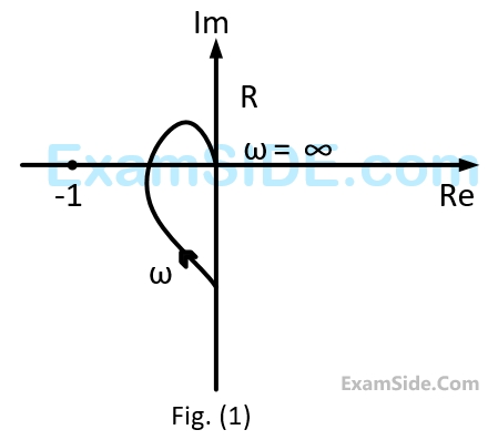
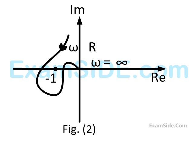
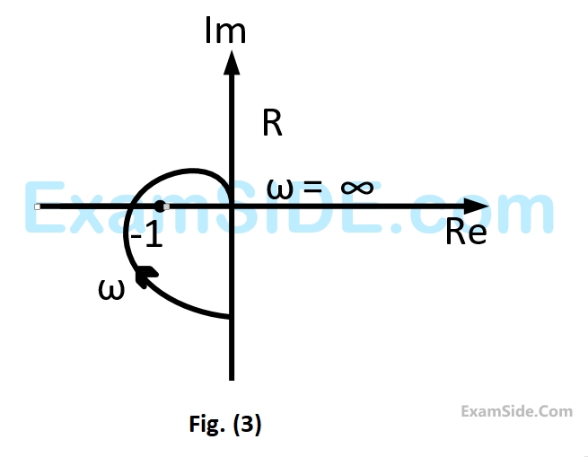
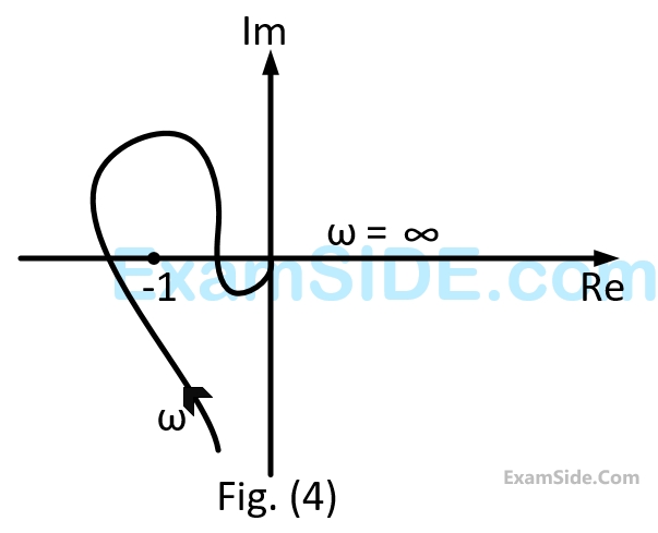
A closed loop system has the characteristic function $$\left( {{s^2} - 4} \right)\left( {s + 1} \right) + K\left( {s - 1} \right) = 0.$$
Its root locus plot against $$K$$ is
11
A
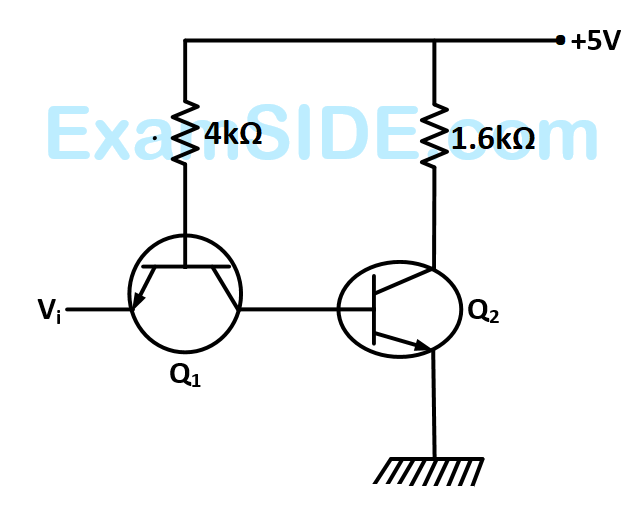
TTL NOT gate circuit is shown in figure. Assuming $${V_{BE}} = 0.7\,v$$ of both the transistors, if $${V_i} = 3.0\,V,$$ then the states of the two transistors will be
12
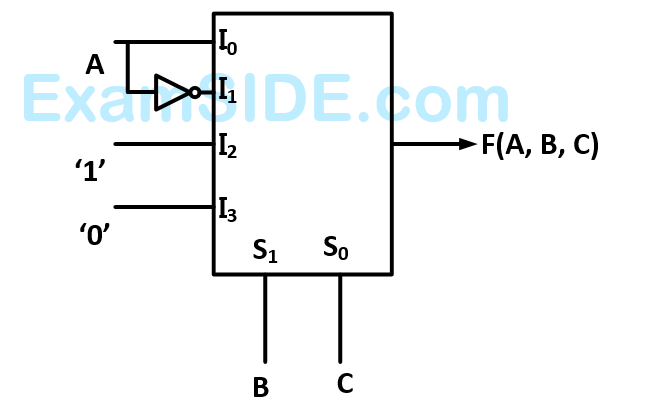
A $$4 \times 1\,\,MUX$$ is used to implement a $$3$$- input Boolean function as shown in figure. The Boolean function $$F\left( {A,\,\,B,\,\,C} \right)$$ implemented is
13
A software delay subroutine is written as given below:

How many times $$DCR$$ $$L$$ instruction will be executed?
14
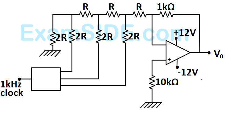
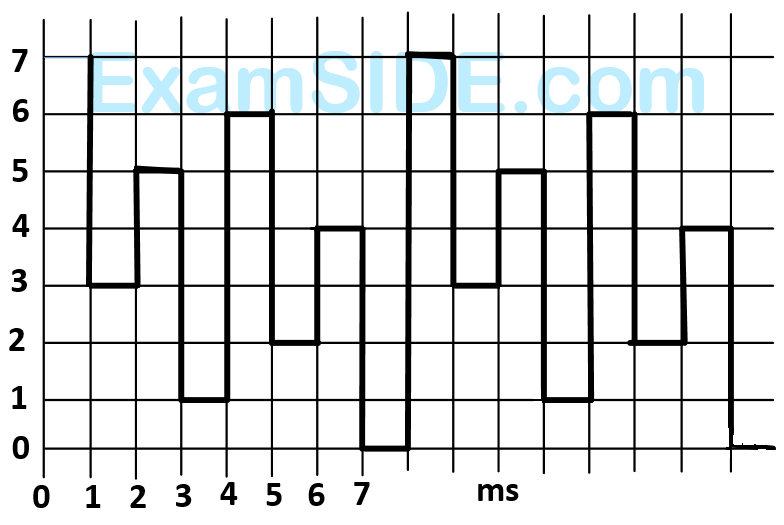
A student has made a-$$3$$ bit binary down counter and connected to the $$R$$-$$2R$$ ladder type $$DAC$$ [Gain $$=$$ $$\left( { - 1k\Omega /2R} \right)$$ as shown in figure to generate a staircase waveform.
The output achieved is different as shown in figure. What could be the possible cause of this error?
15
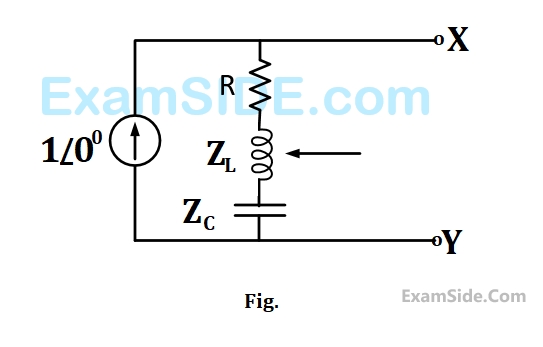
In the figure the current source is $$1\,\,\angle \,0\,A,$$ $$R = \,1\,\,\Omega ,$$ the impedances are $${Z_C} = - j\,\,\Omega ,$$ and $${Z_L} = 2\,j\,\,\Omega .$$ The Thevenin equivalent looking into the circuit across $$X-Y$$ is.
16
A $$400V$$, $$50$$ $$Hz,$$ three phase balanced source supplies power to a star connected load whose rating is $$12\,\,\angle 3\,\,kVA,$$ $$0.8$$ $$pf$$ (lag). The rating $$($$in $$kVAR)$$ of the delta connected (capacitive) reactive power bank necessary to bring the $$pf$$ to unity is
17
The parameters of the circuit shown in the figure are
$${R_i} = 1\,\,M\,\Omega ,\,\,{R_0} = 10\,\Omega ,\,\,A = {10^6}\,\,V/V.$$ If $${V_i} = 1\,\,\mu V,\,\,$$ the output voltage, input impedance and output impedance respectively are

18
The circuit shown in the figure is energized by a sinusoidal voltage source $${V_1}$$ at a frequency which causes resonance with a current of $${\rm I}$$.

The phasor diagram which is applicable to this circuit is
19
An ideal capacitor is charged to a voltage $${V_0}$$ and connected at $$t=0$$ across an ideal inductor $$L.$$ (The circuit now consists of a capacitor and inductor alone). If we let $${\omega _0} = 1/\sqrt {LC} ,$$ the voltage across the capacitor at time $$t>0$$ is given by
20
A variable $$'w'$$ is related to three other variables $$x, y, z$$ as $$w=xy/z.$$ The variables are measured with meters of accuracy$$ \pm $$ $$0.5$$% reading, $$ \pm 1\% $$ of full scale value and $$ \pm 1.5\% $$ reading the actual readings of the three meters are $$80,20$$ and $$50$$ with $$100$$ being the full scale value for all three. The maximum uncertainty in the measurement of $$'w'$$ will be
21
$${R_1}$$ and $${R_2}$$ are the opposite arms of $${R_3}$$ and $${R_4}$$ of a wheat stone bridge. The source voltage is applied across $${R_1}$$ and $${R_3}$$ under balanced conditions, which one of the following is true?
22
A sampling wattmeter (that computes power from simultaneously sampled values of voltage and current) is used to measure the average power of a load. The peak to peak voltage of the square wave is $$10V$$ and the current is triangular wave of $$5A$$ $$p$$-$$p$$ as shown in the figure. The period is $$20$$$$ms$$. The reading in $$W$$ will be

23
The time/div and voltage/div axes of an oscilloscope have been erased. A student connects a 1kHz, 5V p-p square wave calibration pulse to channel-1 of the scope and observes the screen to be as shown in the upper trace of the fig. An unknown signal is connected to channel -2 (lower trace ) of the scope. If the time/div and V/div on both channels are the same, the amplitude (p-p) and period of the unknown signal are respectively.

24
An energy meter connected to an immersion heater (resistive) operating on an $$AC$$ $$230V,$$ $$50$$ $$Hz,$$ $$AC$$ single phase source reads $$2.3$$ units ($$kWh$$) in $$1$$ hour. The heater is removed from the supply and now connected to a $$4000$$ $$V$$ peak to peak square wave source of $$150$$ $$Hz.$$ The power in $$kW$$ dessipated by the heater will be
25
A current of $$ - 8 + 6\sqrt 2 \left( {\sin \,\omega t + {{30}^0}} \right)\,\,A$$ is passed though three meters. They are a center zero $$PMMC$$ meter, true $$r.m.s$$ meter and moving $${\rm I}$$ron instrument. The respective reading (in $$A$$) will be
26
A $$200/1$$ current transformer $$(CT)$$ is wound with $$200$$ turns on the secondary on a toroidal core. When it carries a current of $$160$$ $$A$$ on the primary, the ratio and phase errors of the $$CT$$ are found to be $$-$$ $$50$$% and $$30$$ minutes respectively. If the number of secondary turns is reduced by $$1$$ the new ratio error (%) and phase error (min) will be respectively.
27
The speed of a $$4$$-pole induction motor is controlled by varying the supply frequency while maintaining the ratio of supply voltage to supply frequency $$(V/f)$$ constant. At rated frequency of $$50$$ $$Hz$$ and rated voltage of $$400$$ $$V$$ its speed is $$1440$$ $$rpm$$. Find the speed at $$30$$ $$Hz,$$ if the load torque is constant
28
A synchronous generator is feeding a zero power factor (lagging) load at rated current the armature reaction is
29
A $$3$$ phase, $$4$$ pole, $$400$$ $$V,$$ $$50$$ $$Hz,$$ star connected induction motor has following circuit parameters $${r_1} = 1.0\Omega ,\,{r_2} = 0.5\Omega ,$$ $${\mkern 1mu} {\mkern 1mu} {\mkern 1mu} {x_1} = x{'_2} = 1.2\Omega ,{\mkern 1mu} {x_m} = 35\Omega $$
The starting torque when the motor is started direct-on-line is (use approximate equivalent circuit model)
30
A $$4$$ pole, $$50$$ $$Hz,$$ synchronous generator has $$48$$ slots in which a double layer winding is house. Each coil has $$10$$ turns and is short pitched by an angle to $$36$$ degrees electrical. The fundamental flux per pole is $$0.025$$ $$Wb$$
The line to line induced $$emf$$, for a three phase star connection is approximately
31
A $$3$$-phase $$4000$$ $$V,$$ $$5$$ $$kW,$$ star connected synchronous motor having an internal reactance of $$10$$ $$ohms$$ is operating at $$50\% $$ load, unity power factor. Now, the excitation is increased by $$1\% $$, what will be the new load in percent, if the power factor is to be kept same? Neglect all losses and consider linear magnetic circuit.
32
A $$3$$ phase, $$10$$ $$kW$$, $$400$$ $$V,$$ $$4$$ pole, $$50$$ $$Hz$$, star connected induction motor draws $$20$$ A on full load. Its no load and blocked rotor test data are given below.
No Load Test: $$400V$$ $$6A$$ $$1002W$$
Blocked Rotor Test: $$90V$$ $$15A$$ $$762W$$
Neglecting copper loss in No Load Test and core loss in Blocked Rotor Test, estimate motor's full load efficiency.
33
A $$4$$ pole, $$50$$ $$Hz,$$ synchronous generator has $$48$$ slots in which a double layer winding is house. Each coil has $$10$$ turns and is short pitched by an angle to $$36$$ degrees electrical. The fundamental flux per pole is $$0.025$$ $$Wb$$
The line to line induced $$emf,$$ for two phase connection is
34
A $$300$$ $$kVA$$ transformer has $$95\% $$ efficiency at full load $$0.8$$ $$pf$$ lagging and $$96\% $$ efficiency at half load, unity $$pf.$$
The iron loss $$\left( {{P_i}} \right)$$ in $$kW,$$ under full load operation are
35
A $$220V$$ $$DC$$ machine supplies $$20$$ $$A$$ at $$200V$$ as a generator. The armature resistance is $$0.2$$ ohm. If the machine is now operated as a motor at same terminal voltage and current but with the flux increased by $$10\% ,$$ the ratio of motor speed to generator speed is
36
Two transformers are to be operated in parallel such that they share load in proportion to their $$kVA$$ ratings. The rating of the first transformer is $$500$$ $$kVA$$ and its $$pu$$ leakage impedance is $$0.05$$ $$pu.$$ If the rating of second transformer is $$250$$ $$kVA,$$ its $$pu$$ leakage impedance is
37
In transformers, which of the following statements is valid?
38
In a $$DC$$ machine, which of the following statements is true?
39
A $$300$$ $$kVA$$ transformer has $$95\% $$ efficiency at full load $$0.8$$ $$pf$$ lagging and $$96\% $$ efficiency at half load, unity $$pf.$$
What is the maximum efficiency (in %) at unity $$pf$$ load?
40
Which of the following statements holds for the divergence of electric and magnetic flux densities?
41
The concept of an electrically short, medium, and long line is primarily based on the
42
Consider the following statements with reference to the equation $$\nabla.\overrightarrow J=-\frac{\partial\rho}{\partial t}$$
1. This is a point from the continuity equation
2. Divergence of current density is equal to the decrease of charge per unit volume per unit time at every point.
3. This is Maxwell's divergence equation
4. This represents the conservation of charge.
Select the correct answer.
43
The expression $$V = \int\limits_0^H {\pi {R^2}{{\left( {1 - {h \over H}} \right)}^2}dh\,\,\,} $$ for the volume of a cone is equal to _________.
44
A voltage commutated chopper operating at $$1$$ $$kHz$$ is used to control the speed of $$dc$$ motor as shown in figure. The load current is assumed to be constant at $$10$$ $$A.$$

The minimum time in $$\mu $$ sec for which the $$SCR$$ $$M$$ should be ON is
45
A voltage commutated chopper operating at $$1$$ $$kHz$$ is used to control the speed of $$dc$$ motor as shown in figure. The load current is assumed to be constant at $$10$$ $$A.$$
The average output voltage of the chopper will be
46
A single $$-$$ phase half wave uncontrolled converter circuit is shown in figure. A $$2$$ -winding transformer is used at the input for isolation. Assuming the load current to be constant and $${V_{in}} = {V_m}$$ $$\,\sin \omega t,$$ the current waveform through diode $${D_2}$$ will be

47
A single - phase bridge converter is used to charge a battery of $$200$$ $$V$$ having an internal resistance of $$2\,\,\Omega $$ as shown in figure. The $$SCRs$$ are triggered by a constant $$dc$$ signal. If $$SCR$$ $$2$$ gets open circuited, what will be the average charging current?

48
A voltage commutation circuit is shown in figure. If the turn off time of the $$SCR$$$$s$$ is $$50$$ $$\mu \sec $$ and as safety margin of $$2$$ is considered, what will be the approximate minimum value of capacitor required for proper commutation?

49
An $$SCR$$ having a turn ON time of $$5\,\,\mu \,\,\sec $$, latching current of $$50$$ $$mA$$ and holding current of $$40$$ $$mA$$ is triggered by a short duration pulse and is used in the circuit shown in figure The minimum pulse width required To turn the $$SCR$$ ON will be

50
A solar cell of $$350V$$ is feeding power to an $$ac$$ supply of $$440$$ $$V,$$ $$50$$ $$Hz$$ through a $$3$$- phase fully controlled briodge converter. A large inductance is connected in the $$dc$$ circuit to maintain the $$dc$$ current at $$20A.$$ If the solar cell resistance of $$0.5\Omega ,$$ then each thryristor will be reverse biased for a period of
51
A $$3$$ $$-$$ phase fully controlled bridge converter with free wheeling diode is fed from $$400$$ $$V$$, $$50$$ $$Hz$$ $$AC$$ source and is operating at a firing angle of $${60^ \circ }.$$ The load current is assumed constant at $$10A$$ due to high load inductance The input displacement factor $$(IDF)$$ and the input power factor $$(IPF)$$ of the converter will be
52
For a power system the admittance and impedance matrices for the fault studies are as follows.
$$$\eqalign{
& {Y_{bus}} = \left[ {\matrix{
{ - j8.75} & {j1.25} & {j2.50} \cr
{j1.25} & { - j6.25} & {j2.50} \cr
{j2.50} & {j2.50} & { - j5.00} \cr
} } \right] \cr
& {Z_{bus}} = \left[ {\matrix{
{j0.16} & {j0.08} & {j0.12} \cr
{j0.08} & {j0.24} & {j0.16} \cr
{j0.12} & {j0.16} & {j0.34} \cr
} } \right] \cr} $$$
The pre-fault voltages are $$1.0$$ $$p.u.$$ at all the buses. The system was unloaded prior to the fault. A solid $$3$$ phase fault takes place at bus $$2.$$
The per unit fault feeds from generators connected to buses $$1$$ and $$2$$ respectively are
53
Keeping in view the cost and overall effectiveness, the following circuit breaker is best suited for capacitor bank switching
54
For a power system the admittance and impedance matrices for the fault studies are as follows.
$$$\eqalign{
& {Y_{bus}} = \left[ {\matrix{
{ - j8.75} & {j1.25} & {j2.50} \cr
{j1.25} & { - j6.25} & {j2.50} \cr
{j2.50} & {j2.50} & { - j5.00} \cr
} } \right] \cr
& {Z_{bus}} = \left[ {\matrix{
{j0.16} & {j0.08} & {j0.12} \cr
{j0.08} & {j0.24} & {j0.16} \cr
{j0.12} & {j0.16} & {j0.34} \cr
} } \right] \cr} $$$
The pre-fault voltages are $$1.0$$ $$p.u.$$ at all the buses. The system was unloaded prior to the fault. A solid $$3$$ phase fault takes place at bus $$2.$$
The post fault voltages at buses $$1$$ and $$3$$ in per unit respectively are
55
A generator is connected through a $$20$$ MVA, $$13.8/138$$ kV step up transformer, to a transmission line. At the receiving end of the line a load is supplied through a step down transformer of $$10$$ MVA, $$138/69$$ kV rating. A $$0.72$$ p.u. load, evaluated, on load side transformer ratings as base values of $$10$$ MVA and $$69$$ kV in load circuit, the value of the load (in per unit) in generator circuit will be
56
Three identical star connected resistors of $$1.0$$ $$p.u$$ are connected to an unbalanced $$3$$ phase supply. The load neutral is isolated. The symmetrical components of the line voltages in $$p.u.$$ calculations are with the respective base values, the phase to neutral sequence voltages are
57
The Gauss Seidel load flow method has following disadvantages. Tick the incorrect student.
58
An HVDC link consists of rectifier, inverter transmission line and other equipments. Which one of the following is true for this link?
59
In a biased differential relay the bias is defined as a ratio of
60
A $$400$$ V, $$50$$ Hz, three phase balanced source supplies power to a star connected load whose rating is $$12\sqrt 3 $$ kVA, $$0.8$$ pf(lag). The rating (in kVAR) of the delta connected (capacitive) reactive power bank neccessary to bring the pf to unity is
61
The concept of an electricity short, medium and long line is primarily based on the
62
A generator feeds power to an infinite bus through a double circuit transmission line. A $$3$$ phase fault occurs at the middle point of one of the lines. The infinite bus voltage is $$1$$ pu, the transient internal voltage of the generator is $$1.1$$ pu and the equivalent transfer admittance during fault is $$0.8$$ pu. The 100 MVA generator has an inertia constant of $$5$$ MJ/MVA and it was delivering $$1.0$$ pu power prior of the fault with rotor power angle of $${30^ \circ }\,\,$$. The system frequency is 50Hz.
If the initial accelerating power is $$X$$ pu, the initial acceleration in elect deg/sec2, and the inertia constant in MJ-sec/elect deg respectively will be
63
The $$A, B, C, D$$ constant of a $$220$$ $$kV$$ line are:
$$A = D = 0.94\,\angle \,10,\,\,\,B = 130\,\angle \,730,\,\,\,C = 0.001\,\angle \,900.\,\,$$ If the sending end voltage of the line for a given load delivered at nominal voltage is $$240$$ $$kV$$, the % voltage regulation of the line is
64
A generator feeds power to an infinite bus through a double circuit transmission line. A 3 phase fault occurs at the middle point of one of the lines. The infinite bus voltage is 1 pu, the transient internal voltage of the generator is 1.1 pu and the equivalent transfer admittance during fault is 0.8 pu. The 100 MVA generator has an inertia constant of $$5$$ MJ/MVA and it was delivering 1.0 pu power prior of the fault with rotor power angle of $${30^ \circ }\,\,$$. The system frequency is 50Hz.
The initial accelerating power (in pu) will be
65
A continuous-time system is described by $$y\left( t \right) = {e^{ - |x\left( t \right)|}},$$ where $$y(t)$$ is the output and $$x(t)$$ is the input. $$y(t)$$ is bounded
66
A discrete real all pass system has a pole at $$z = 2\angle {30^ \circ };\,$$ it, therefore,
67
$$x(t)$$ is a real valued function of a real variable with period $$T.$$ Its trigonometric. Fourier Series expansion contains no terms of frequency
$$\omega = 2\pi \left( {2k} \right)/T;\,\,k = 1,2,........$$ Also, no sine terms are present. Then $$x(t)$$ satisfies the equation
68
$$y\left[ n \right]$$ denotes the output and $$x\left[ n \right]$$ denotes the input of a discrete-time system given by the difference equation $$y\left[ n \right] - 0.8y\left[ {n - 1} \right] = x\left[ n \right] + 1.25\,x\left[ {n + 1} \right].$$ Its right-sided impulse response is
69
$$x\left[ n \right] = 0;\,n < - 1,\,n > 0,\,x\left[ { - 1} \right] = - 1,\,x\left[ 0 \right]$$
$$\,\,\,\,\,\,\,\,\,\,\,\,\,\,\,\,\,\,\,\,\,\,\,\,\,\,\,\,\,\,\,\, = 2$$ is the input and
$$y\left[ n \right] = 0;\,n < - 1,\,n > 2,\,y\left[ { - 1} \right] = - 1,\, = y\left[ 1 \right],\,y\left[ 0 \right] = 3,\,y\left[ 2 \right]$$
$$\,\,\,\,\,\,\,\,\,\,\,\,\,\,\,\,\,\,\,\,\,\,\,\,\,\,\,\,\,\,\,\, =- 2$$ is the output of a discrete-time $$LTI$$ system. The system impulse response $$h\left[ n \right]$$ will be
70
The discrete-time signal $$$x\left[n\right]\leftrightarrow X\left(z\right)={\textstyle\sum_{n=0}^\infty}\frac{3^n}{2+n}z^{2n}$$$
where $$\leftrightarrow$$ denote a transform-pair relationship, is orthogonal to the signal