GATE EE 1999
GATE EE
1
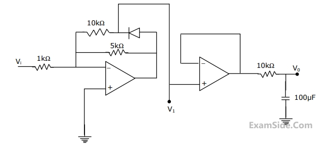
The input voltage $${V_i}$$ in the circuit is a $$1$$ $$kHz$$ sine wave of $$1$$ $$V$$ amplitude. Assume ideal operational amplifiers with $$ \pm 15V\,\,DC$$ supply. Sketch on a single diagram the wave-forms of $${V_i},$$ $${V_1}$$ and $${V_0}$$ show, indicating the peak value of$${V_1}$$ and the average value $${V_0}$$.
2
The enhancement type n-channel MOSFET is represented by the symbol
3
The mobility of an electron in a conductor expressed in terms of
4
The colour code of a $$1k\Omega $$ resistance is
5
As temperature is increased, the voltage across a diode carrying a constant current.
6
For the small signal $$BJT$$ amplifier shown in given figure. Determine at $$1$$ $$kHz$$ the following
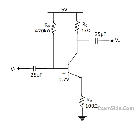
$$(a)$$ $$\,\,\,\,\,\,\,\,$$ Quiescent collector current $${{\rm I}_{CQ}}$$
$$(b)$$ $$\,\,\,\,\,\,\,\,$$ Small signal voltage gain $${{{V_o}} \over {{V_i}}}$$
$$(c)$$ $$\,\,\,\,\,\,\,\,$$ Max. possible swing of the collector current.
7
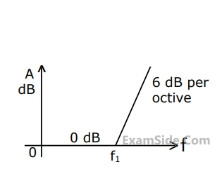
The function corresponding to the Bode plot of Figure, is
8
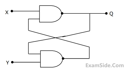
For a flip-flop formed from two $$NAND$$ gates as shown in figure. The unusable state corresponds to
9
The logic function $$f = \overline {\left( {x.\overline y } \right) + \left( {\overline x .y} \right)} $$ is the same as
10
The logic function $$F = AC + ABD + ACD$$ is to be realized using an $$8$$ to $$1$$ multiplexer shown in figure, using $$A, C$$ and $$D$$ as control inputs.
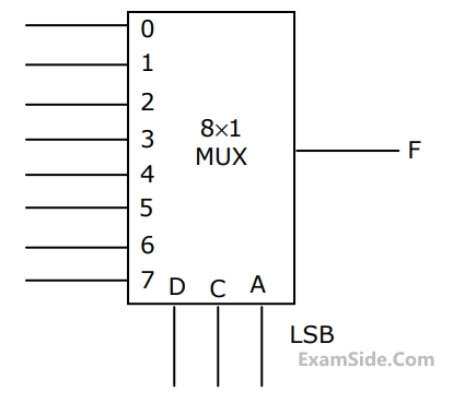
$$(a)$$ Indicate the inputs to be applied at the terminals $$0$$ to $$7.$$
$$(b)$$ Can the function be realize using a $$4$$ to $$1$$ multiplexer?
State YES or NO.
11
For a dual $$ADC$$ type $$3\,{\raise0.5ex\hbox{$\scriptstyle 1$}
\kern-0.1em/\kern-0.15em
\lower0.25ex\hbox{$\scriptstyle 2$}}$$ digit $$DVM$$, the reference voltage is $$100$$ $$mV$$ and the first integration time is set to $$300$$ $$ms$$. For some input voltage, the ''deintegration'' period is $$370.2ms.$$ The $$DVM$$ will indicate.
12
When a resistor $$R$$ is connected to a current source, it consumes a power of $$18$$ $$W.$$ when the same $$R$$ is connected to a voltage source having the same magnitude as the current source, the power absorbed by $$R$$ is $$4.5$$ $$W.$$ The magnitude of the current source and the value of $$R$$ are
13
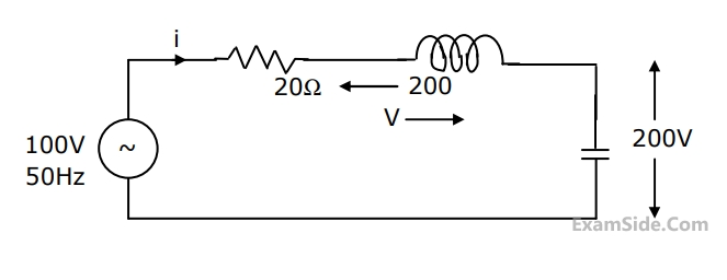
The current in the circuit shown in figure is
14
When a periodic triangular voltage peak amplitude $$1$$ $$V$$ and frequency $$0.5$$ $$Hz$$ is applied to a parallel combination of $$1\,\Omega $$ resistance and $$1$$ $$F$$ capacitance, the current through the voltage source has wave-form
15
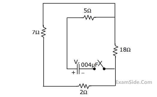
In the given circuit, the capacitor is initially charged to $$12$$ $$V. $$ Find the mathematical expression for the voltage across the capacitor $${{V_C}}$$ after closing the switch at $$t = 0.$$
16
A rectangular voltage pulse of magnitude $$V$$ and duration $$T$$ is applied to a series combination of resistance $$R$$ and capacitance $$C.$$ The maximum voltage developed across the capacitor is
17
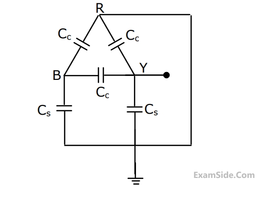
For the circuit shown in Figure, the capacitance measured between terminals $$B$$ and $$Y$$ will be
18
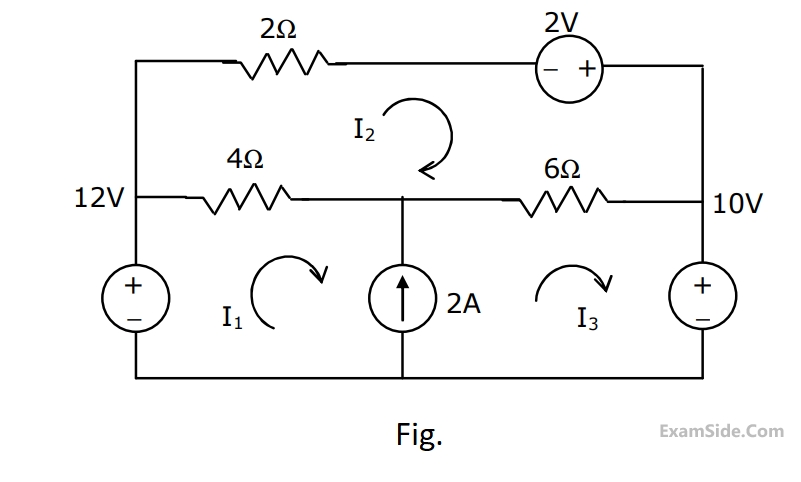
Solve the circuit shown in Fig. using the mesh method of analysis and determine the mesh currents $${{\rm I}_1},\,{{\rm I}_2},$$ and $${{\rm I}_3}$$. Evaluate the power developed in the $$10$$ $$V$$ voltage source.
19
Currents $${{\rm I}_1},\,{{\rm I}_2}$$ and $${{\rm I}_3}$$ meet at a junction (node) in a circuit. All currents are marked as entering the node. If $${{\rm I}_1} = - 6\sin \left( {\omega t} \right)$$ $$mA$$ and $${{\rm I}_2} = 8\cos \,\left( {\omega t} \right)\,mA,$$ then $${{\rm I}_3}$$ will be
20
A series $$R-L-C$$ circuit when excited by a $$10$$ $$V$$ sinusoidal voltage source of variable frequency, exhibits resonance at $$100$$ $$Hz$$ and has a $$3$$ $$dB$$ bandwidth of $$5$$ $$Hz.$$ The voltage across the inductor $$L$$ at resonace is
21
The $$RMS$$ value of half $$-$$ wave rectified symmetrical square wave current of $$2A$$ is
22
A fixed capacitor of reactance –$$j0.02$$ $$\Omega $$ is connected in parallel across a series combination of a fixed inductor of reactance $$j0.01$$ $$\Omega $$ and a variable resistance $$R.$$ As $$R$$ is varied from zero to infinity, the locus diagram of the admittance of this $$L-C-R$$ circuit will be
23
The voltage phasor of a circuit is $$10\angle {15^0}\,V$$ and the current phasor is $$2\,\,\angle - {45^0}A.$$ The active and the reactive powers in the circuit are
24
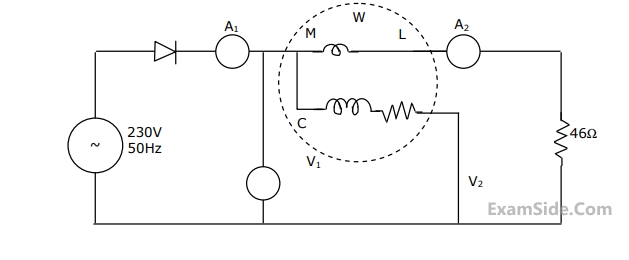
For the given circuit the internal resistance of the ammeters as well as that of the current coil of the wattmeter are zero, and the voltmeters have a very large figure of merit. $${A_1}$$ is a $$6A$$ full scale moving $${\rm I}$$ron type meter. $${A_2}$$ is a commercial full wave rectifier type meter of full scale $$5A$$. $${V_1}$$ is a $$500V$$ meter is an peak response type. $${V_2}$$ is a $$300V$$ $$PMMC$$ type meter and $$W$$ is an electro dynamometer type, $$5A$$, $$230V$$ wattmeter. Determine the readings of $${A_1},$$ $${A_2},$$ $${V_1},$$ $${V_2},$$ and $$W.$$
25
The voltage phasor of a circuit is $$10\angle {15^ \circ }V$$ and the current phasor is $$2\angle - {45^ \circ }A.$$ The active and the reactive powers in the circuit are
26
Electro dynamic type watt meters have large errors while measuring power in a.c circuits at low power factor conditions, since the voltage across and the current though the
27
Two $$100$$ $$\mu A$$ full scale $$PMMC$$ meters are employed to construct a $$10$$ $$V$$ and a $$100$$ $$V$$ full scale voltmeter. These meters will have figures of merit (sensitivities) as
28
For a dual $$ADC$$ type $$3\,\,{1 \over 2}$$ digit $$DVM$$, the reference voltage is $$100mV$$ and the first integration time is set to $$300$$$$ms$$. For some input voltage, the ''deintegration'' period is $$370.2ms$$. The $$DVM$$ will indicate
29
A current of $$\left[ {2 + \sqrt 2 \sin \left( {314t + 30} \right) + 2\sqrt 2 \cos \left( {952t + 45} \right)} \right]$$ is measured with a thermocouple type. $$5A$$ full scale, class $$1$$ meter. The meter reading would like in the range,
30
Two single phase transformers $$A$$ and $$B$$ have the following parameters.
Transformer $$A$$: $$400V/200V,$$ $$10$$ $$kVA,$$ percentage resistance and percentage reactance are $$3\% $$ and $$4\% $$ respectively.
Transformer B: $$5$$ $$kVA,$$ $$400V/200V,$$ percentage resistance and percentage reactance are $$4\% $$ and $$3\% $$ respectively.
These two transformers are connected in parallel and they share a common load of $$12$$ $$kW$$ at a power factor of $$0.8$$ lag. Determine the active and reactive power delivered by transformer $$A.$$
31
A separately excited $$DC$$ shunt motor is driving a fan load whose torque is proportional to the square of the speed. When $$100$$ $$V$$ are applied to the motor, the current taken by the motor is $$8$$ $$A,$$ with the speed being $$500$$ $$rpm.$$ At what applied voltage does the speed reach $$750$$ $$rpm$$ and then what is the current drawn by the armature? Assume the armature circuit resistance to be $$1\,\,\,\Omega .$$ Neglect brush drop and mechanical losses.
32
The following starting method for an induction motor is inferior view of the poor
starting torque per ampere of the line current drawn:
33
A 4-pole lap-wound DC generator has a developed power of P watts and voltage
of E volts. Two adjacent brushes of the machine are removed as they are worn
out. If the machine operates with the remaining brushes, the developed voltage
and power that can be obtained from the machine are
34
A 400V/100V, 10 kVA two-winding transformer is reconnected as an autotransformer
across a suitable voltage source. The maximum rating of such an
arrangement could be
35
Starting torque can be obtained in the case of a single phase induction motor
with identical main and auxiliary windings by connecting
36
A 10 kVA, 400 V/200 V single-phase transformers with 10% impedance draws a
steady short circuit line current of
37
The windings of a Q kVA, $$\frac{V_1}{V_2}$$
Volt, three-phase, Delta connected, core type
transformer are reconnected to work as a single phase transformer. The
maximum voltage and the power ratings of the new configuration are,
38
The percentage resistance and percentage reactance of a 10 kVA, 400 V/200 V,
3-phase transformer are 2% and 10% respectively. If the constant losses in the
machine are 1%, the maximum possible percentage efficiency of the transformer
is:
39
A DC shunt motor is running at 1200 rmp, when excited with 220 V DC.
Neglecting the losses and saturation, the speed of the motor when connected to a
175 V DC supply is:
40
A 10 kVA, 400 V/200 V, single phase transformer with a percentage resistance
of 3% and percentage reactance of 6% is supplying a current of 50 A to a
resistive load. The value of the load voltage is:
41
A three phase alternator is wound with a 60 degree phase-spread armature
windings and develops 300 kVA. If the armature is reconnected utilizing all the
coils for single phase operation with a phase spread of 180 degrees, the new
rating of the machine is
42
Higher synchronous reactance is preferred in the present day alternators,
because one can have
43
A charge $$+Q$$ is uniformly distributed throughout the volume of a dielectric sphere of radius $$R$$ and dielectric constant $$'{\varepsilon _R}'.$$ Based on Gauss law, determine the expressions for the electric field $$E$$ as a function of distance $$'r'$$ from the center of the sphere, within the ranges $$0 < r < R$$ and $$R \le r.$$ Indicate expression $$(s)$$ for the
critical point $$(s)$$ on the sketch.
44
Two parallel wires separated by a distance $$'d'$$ are carrying a current $$'{\rm I}'$$ in the same direction. The magnetic field along a line running parallel to these wires at midway between them
45
An electromagnetic field is radiated from
46
If $$A = \left[ {\matrix{
1 & { - 2} & { - 1} \cr
2 & 3 & 1 \cr
0 & 5 & { - 2} \cr
} } \right]$$ and $$adj (A)$$ $$ = \left[ {\matrix{
{ - 11} & { - 9} & 1 \cr
4 & { - 2} & { - 3} \cr
{10} & k & 7 \cr
} } \right]$$ then $$k=$$
47
Find the eigen values and eigen vectors of the matrix $$\left[ {\matrix{
3 & { - 1} \cr
{ - 1} & 3 \cr
} } \right]$$
48
Resonant Converter's are basically used to
49
A $$PWM$$ switching scheme is used with a three phase inverter to
50
A three phase diode bridge is used to provide rectified output from a $$400V,$$ $$50$$ $$Hz,$$ $$3$$- phase supply to a $$R$$ $$-$$ $$L$$ load with $$10\,\,\Omega $$ resistance and $$300$$ $$mH$$ inductance.
Determine the
(a)$$DC$$ level of the output voltage
(b) $$RMS$$ value of the diode current
(c) $$RMS$$ value of the source current, and
(d) Apparent power drawn from the mains
Determine the
(a)$$DC$$ level of the output voltage
(b) $$RMS$$ value of the diode current
(c) $$RMS$$ value of the source current, and
(d) Apparent power drawn from the mains
51
An industrial consumer has a daily load pattern of $$2000$$ $$kW$$, $$0.8$$ lag for $$12$$ Hrs. and $$1000$$ $$kW$$ $$UPF$$ for $$12$$ Hrs. The load factor is
52
A 66 kV, 3-phase, 50 Hz, 150 km long overhead transmission line is open circuited at the receiving end. Each conductor has a resistance of 0.25$$\Omega $$/km, an inductive reactance of 0.5$$\Omega $$/km and a capacitive admittance to neutral of 0.04 $$ \times $$ 10-4 S/km.
(a) Draw the nominal π-equivalent circuit and indicate the value of each parameter.
(b) Calculate the receiving end voltage if the sending end voltage is 66 kV.
53
The load carrying capability of a long AC transmission line is
54
For a single phase overhead line having solid copper conductors of diameter $$1$$ cm, spaced $$60$$ cm between centers, the inductance in $$mH/km$$ is
55
A 6.6 kV, 50 Hz single core lead sheathed cable has the following data:
Conductor diameter: 1.5 cm, length: 4 km. Internal diameter of the sheath : 3 cm
Resistivity of insulation : 1.3 $$ \times $$ 1012 $$\Omega $$-m. Relative permittivity of insulation : 3.5 Calculate
Conductor diameter: 1.5 cm, length: 4 km. Internal diameter of the sheath : 3 cm
Resistivity of insulation : 1.3 $$ \times $$ 1012 $$\Omega $$-m. Relative permittivity of insulation : 3.5 Calculate
(a) the insulation resistance
(b) the capacitance and
(c) the maximum electric stress in the insulation
56
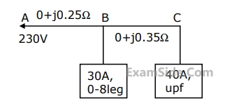
A single phase AC distributor supplies two single phase loads as shown in figure. The voltage drop from A to C is
57
$$A$$ $$220$$ kV, $$20$$ km long, $$3$$-phase transmission line has the following $$A, B, C, D$$ constants. $$A=D=0.96$$$$\angle {3^0},$$ $$\,B = 55\angle {65^0}\,\,\Omega /$$ phase, $$\,C = 0.5 \times {10^{ - 4}}\angle {90^0}\,\,$$ $$S/$$phase. Its correct charging current per phase is
58
Steady state stability of a power system is the ability of the power system to
59
An overhead line having a surge impedance of $$400$$$$\Omega $$ is connected in series with an underground cable having a surge impedance of $$100$$$$\Omega $$. If a surge of $$50$$ $$kV$$ travels from the line end towards the cable junctions, the value of the transmitted voltage wave at the junction is
60
A 3-phase, 11 kV, 50 Hz, 200 kW load has a power factor of 0.8 lag. A delta connected 3-phase capacitor is used to improve the power factor to unity. The capacitance power phase of the capacitor in micro-farads is
61
Corona losses are minimized when
62
Determine the magnitudes of the symmetrical components ($${{{\rm I}_{R1}},\,{{\rm I}_{R2}}\,}$$ and $${{{\rm I}_{R0}}}$$) of the currents in a three phase (RYB) three wire system, when a short circuit occurs between R and Y phase wires, the fault current being 100 A.
63
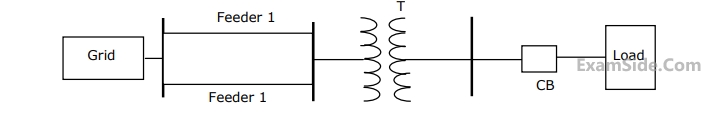
Determine the required MVA rating of the circuit breaker CB for the system shown in given figure. Consider the grid as infinite bus. Choose 6 MVA as base. Transformer 3-phase, 33/11 kV, 6 MVA, 0.01+j0.08 p.u. impedance. Load 3-phase 11 kV, 5800 kVA, 0.8 lag, j0.2 p.u. impedance. Impedance of each feeder 9+j 18 $$\Omega $$.
64
Three sections of a feeder are provided with circuit breakers CB1, CB2, CB3, CB4, CB5 and CB6. For a fault F as indicated in figure.
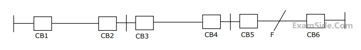
65
A rectangular current pulse of duration T and magnitude 1 has the Laplace transform