GATE EE 2000
View Questions

GATE EE

1
An analog electronic circuit that measures $$rms$$ value of the input voltage by averaging the square of the instantaneous voltage level, responds slowly to changes in the input signal due to
2
An active filter consisting of an op-amp, resistor $${R_1},\,\,{R_2},\,\,{R_3}$$ and two capacitors of value $$C$$ each, has a transfer function
$$T\left( s \right) = {{{{ - s} \over {\left( {{R_1}C} \right)}}} \over {{s^2} + {{2s} \over {\left( {{R_3}C} \right)}} + {1 \over {\left( {R{R_3}{C^2}} \right)}}}}$$
where, $$R = {R_1}||{R_2}$$
If $${R_1} = 2k\Omega ,{R_2} = 2/3\,k\Omega ,\,\,{R_3} = 200\,k\Omega $$ and $$C = 0.1\,\,\mu F,$$ determine the center frequency $${\omega _0},$$ gain $${A_0}$$ and the $$Q$$ of the filter.
3
The feedback factor for the circuit shown in fig. is GATE EE 2000 Analog Electronics - Operational Amplifier Question 63 English
4
A current amplifier has an input resistance of $$10\Omega ,$$ an output resistance of $$10\,\,k\Omega $$ and a Current gain of $$1000.$$ It is feed by a current source having a source resistance of $$10$$ $$k\Omega $$ and its output connected to a $$10\,\,k\Omega $$ load resistance. Find the voltage gain and the power gain
5
In the circuit of figure, the value of the base current $${{\rm I}_B}$$ will be GATE EE 2000 Analog Electronics - Bjt and Mosfet Biasing Question 21 English
6
The type of power amplifier which exhibits crossover distortion in its output is
7
The circuit shown in figure uses an ideal op-amp working with $$+5V$$ and $$-5V$$ power supplies. The output voltage $${V_0}$$ is equal to GATE EE 2000 Analog Electronics - Operational Amplifier Question 64 English
8
Feedback control systems are
9
A linear time-invariant system initially at rest, when subjected to a unit-step input, gives a response $$y\left( t \right) = t{e^{ - t}},\,\,t > 0.$$ The transfer function of the system is:
10
A unity feedback system has open loop transfer function $$G(s).$$ The steady-state error is zero for
11
A unity feedback system has open-loop transfer function $$G\left( s \right) = {{25} \over {s\left( {s + 6} \right)}}.$$ The peak overshoot in the step-input response of the system is approximately equal to
12
A unity feedback system has open loop transfer function $$G\left( s \right) = {{K\left( {s + 5} \right)} \over {s\left( {s + 2} \right)}};K \ge 0$$
(a) Draw a rough sketch of the root locus plot; given that the complex roots ofthe characteristic equation move along a circle.
(b) As K increases, does the system become less stable? Justify your answer.
(c) Find the value of $$K$$ (if it exists) so that the damping $$\xi $$ of the complex closed loop poles is $$0.3.$$
13
Open-loop transfer function of a unity - feedback system is $$$G\left( s \right) = {G_1}\left( s \right).{e^{ - s{\tau _D}}} = {{{e^{ - s{\tau _D}}}} \over {s\left( {s + 1} \right)\left( {s + 2} \right)}}$$$
Given : $$\,\left| {{G_1}\left( {j\omega } \right)} \right| \approx 1$$ when $$\omega = 0.446$$

(a) Determine the phase margin when $${\tau _D} = 0$$
(b) Comment in one sentence on the effect of dead time on the stability of the system.
(c) Determine the maximum value of dead time $${\tau _D}$$ for the closed-loop system to be stable.

14
$$D\left( s \right) = {{\left( {0.5s + 1} \right)} \over {\left( {0.05s + 1} \right)}}$$ Maximum phase lead of the compensator is
15
Consider the state equation $$\mathop X\limits^ \bullet \left( t \right) = Ax\left( t \right)$$
Given : $${e^{AT}} = \left[ {\matrix{ {{e^{ - t}} + t{e^{ - t}}} & {t{e^{ - t}}} \cr { - t{e^{ - t}}} & {{e^{ - t}} - t{e^{ - t}}} \cr } } \right]$$

(a) Find a set of states $${x_1}\left( 1 \right)$$ and $${x_2}\left( 1 \right)$$ such that $${x_1}\left( 2 \right) = 2.$$
(b) Show that $$\,{\left( {s{\rm I} - A} \right)^{ - t}} = \Phi \left( s \right) = {1 \over \Delta }\left[ {\matrix{ {s + 2} & 1 \cr { - 1} & s \cr } } \right];$$ $$\Delta = {\left( {s + 1} \right)^2}$$
(c) From $$\Phi \left( s \right),$$ find the matrix $$A$$.

16
The minimal product-of-sums function described by the $$K$$-map given in Fig. GATE EE 2000 Digital Electronics - Combinational Circuits Question 9 English
17
A dual-slope analog-to-digital converter uses an $$N$$-bit counter. When the input signal $${V_a}$$ is being integrated, the counter is allowed to count up to a value:
18
The counter shown in Fig. is initially in state $${Q_2} = 0,\,{Q_1} = 1,\,{Q_0} = 0.$$ With reference to the $$CLK$$ input, draw waveforms for $${Q_2},{Q_1},{Q_0}$$ and $$P$$ for the next three $$CLK$$ cycles. GATE EE 2000 Digital Electronics - Sequential Circuits Question 19 English
19
Which one of the following is not a vected interrupt?
20
A voltage wafeform $$v\left( t \right) = 12\,{t^2}$$ is applied across a $$1$$ $$H$$ inductor for $$t \ge 0,$$ with initial current through it being zero. The current through the inductor for $$t \ge 0$$ is given by:
21
The circuit shown Fig. is equivalent to a load of GATE EE 2000 Electric Circuits - Network Elements Question 23 English
22
Predict the current $${\rm I}$$ in Fig. in response to a voltage of $$20\angle {0^0}\,V.$$ The impedance values are given in $$ohms.$$ Use Thevenin's theorem. GATE EE 2000 Electric Circuits - Network Theorems Question 15 English
23
The impedance seen by the source in the circuit in Fig. is given by GATE EE 2000 Electric Circuits - Sinusoidal Steady State Analysis Question 22 English
24
If an $$ac$$ voltage wave is corrupted with an arbitrary number of harmonics, then the overall voltage waveform differs from its fundamental frequency component in terms of
25
A two-port device is defined by the following pair of equations:
$${i_1} = 2{v_1} + {v_2}$$ and $${i_2} = {v_1} + {v_2}$$
Its impedance parameters $$\left( {{z_{11}},\,\,{z_{12}},\,\,{z_{21}},\,\,{z_{22}}} \right)$$ are given by
26
The two wattmeter method is used to measure active power on a three phase, three wire system. If the phase voltage is unbalanced, then the power reading is
27
A $$3$$ - $$\phi $$ load operates with balanced voltages applied to its terminals, and draws balanced currents. The potential coil of a moving coil wattmeter is connected from $$R$$ to $$Y$$ terminals of the load. The current coil of the meter is connected in series with phase $$B.$$ by appropriate derivation, show that the quantity indicated by this wattmeter is proportional to the reactive power drawn by the load
28
Instrument transformers are known to introduce magnitude and phase errors in measurements. These are primarily due to
29
A $$2300$$ $$V,$$ $$3$$-phase synchronous motor driving a pump is provided with a line ammeter and a field rheostat. When the rheostat is adjusted such that the $$ac$$ line current is minimum. The ammeter reads $$8.8$$ $$A.$$ What is the power being delivered to the pump, neglecting losses? How should the rheostat be adjusted so that the motor operates at $$0.8$$ leading power factor? How many $$kVARs$$ is the motor supplying to the system at this new power factor?
30
Ratio of the rotor reactance X to the rotor resistance R for a two-phase servomotor
31
A 1.8° step, 4-phase stepper motor has a total of 40 teeth on 8 poles of stator. The number of rotor teeth for this motor will be
32
A 240 V dc series motor takes 40A when giving its rated output at 1500 rpm. Its resistance is 0.3 ohms. The value of resistance which must be added to obtain rated torque at 1000 rpm is:
33
A permanent magnet dc commutator motor has a no load speed of 6000 rpm when connected to a 120V dc supply. The armature resistance is 2.5 ohms and other losses may be neglected. The speed of the motor with supply voltage of 60V developing a torque 0.5 Nm, is:
34
In a constant voltage transformer (CVT), the output voltage remains constant due to
35
If an ac voltage wave is corrupted with an arbitrary number of harmonics, then the overall voltage waveform differs from its fundamental frequency component in terms of
36
A 3-phase delta/star transformer is supplied at 6000 V on the delta-connected side. The terminal voltage on the secondary side when supplying full load as 0.8 lagging power-factor is 415 V. The equivalent resistance and reactance drops for the transformer are 1% and 5% respectively. The turn's ratio of the transformer is:
37
A three phase, wound rotor induction motor is to be operated with slip energy recovery in the constant torque mode, when it delivers an output power P0 at slop 's'. then theoretically, the maximum power that is available for recovery at the rotor terminals, is equal to
38
The power input to a 415 V, 50 Hz, 6 pole, 3-phase induction motor running at 975 rpm is 40 kW. The stator losses are 1kW and friction and windage losses total 2 kW. The efficiency of the motor is
39
A 3-phase, 4-pole squirrel cage induction motor has 36 stator and 28 rotor slots. The number of phases in the rotor is:
40
The phase sequence of a three-phase alternator will reverse if
41
A single-phase, 2000 V alternator has armature resistance and reactance of 0.8 ohms and 4.94 ohms respectively. The voltage regulation of the alternator at 100 A load at 0.8 leading power-factor is:
42
The compensating winding in a dc machine
43
Show via the construction of a suitable Gaussian surface, that the capacitance of a spherical capacitor consisting of two concentric shells of radii $$a$$ and $$b$$ is given by $$C = 4\pi {\varepsilon _0}{{ab} \over {\left( {b - a} \right)}}$$ where $${\varepsilon _0}$$ is the free space permittivity.
44
An electron with velocity $$'u'$$ is placed in an electric field, $$E$$ and magnetic field, $$B.$$ The force experienced by the electron is given by
45
A current $${\rm I}$$ in the short conducting element shown in Fig. produces a flux density $${B_1}$$ at point $$1.$$ Determine the magnitude and the direction of the flux density vector at point $$2$$ GATE EE 2000 Electromagnetic Fields - Magnetostatics Question 8 English
46
A thyristorised three phase fully controlled converter feeds a $$dc$$ load that draws a constant current. Then the input $$ac$$ line current to the converter has
47
A step down chopper operates from a $$dc$$ voltage source $${V_s}$$ feeds a $$dc$$ motor armature with a back $$e.m.f$$ $$\,\,{E_b}.$$ From oscilloscope traces, it is found that the current increases for time $${t_r}$$ falls to zero over time $${t_f},$$ and remains zero for time $${t_0}$$ in every chopping cycle, then the average $$dc$$ voltage across the freewheeling diode is
48
A $$dc$$ motor with armature resistance $${R_a}$$ is fed from a step down chopper in the continuous mode, and operates at some known speed and known excitation current. The motor current rises from $${I_{\min }}\,\,$$ to $${I_{\max }}\,\,$$ in the $${T_{on}}$$ period Ton of the chopper; and drops from $${I_{\max }}\,\,$$ to $${I_{\min }}\,\,$$ in the $${T_{off}}$$ period Toff of the same circuit. Both the rise and fall of the current may be assumed to be approximately linear. What is the average power loss in the machine armature?
49
Triangular $$PWM$$ control, when applied to a $$BJT$$ based three phase voltage source inverter, introduces.
50
A three phase voltage source inverter supplies a purely inductive three phase load. Upon Fourier analysis, the output voltage waveform is found to have an $${h^{th}}$$ order harmonic of magnitude α h times that of the fundamental frequency component $$\left( {{\alpha _h} < 1} \right),$$ the load current would then have an $${h^{th}}$$ order harmonic of magnitude
51
A single phase voltage source of magnitude $${V_s}$$ and frequency $$\omega \,\,\left( {rad\,/\,\sec } \right)$$ is connected to an inductance $$L$$ through an antiparallel back-to-back pair of thyristors. The forward and reverse conducting thyristors are fired at an angle of $$\alpha \ge \pi /2$$ from the positive going and negative going zer crossings of the supply voltage respectively, in each cycle. Obtain an expression for the inductor current in each cycle for a given value of $$\alpha .$$ The voltage drop across the thyristors, when either of them is in conduction, may be assumed to be negligible.
52
The incremental cost characteristic of two generators delivering $$200$$ $$MW$$ are as follows $$\,\,\,{{d{F_1}} \over {d{P_1}}} = 20 + 0.1{P_1},\,\,{{d{F_2}} \over {d{P_2}}} = 16 + 0.2{P_2}$$
For economic operation, the generations $${P_1}$$ and $${P_2}$$ should be
53
A transmission line has equal voltages at the two ends, maintained constant by two sources. A third source is to be provided to maintain constant voltage (equal to end voltages) at either the midpoint of the line or at $$75$$% of the distance from the sending end. Then the maximum power transfer capabilities of the line in the original case and the other two cases respectively will be in the following ratios.
54
The corona loss on a particular system at 50 Hz is 1 kW/km per phase. The corona loss at 60 Hz would be
55
A $$275$$ $$kV,$$ $$3$$-phase, $$50$$ $$Hz,$$ $$400$$ $$km$$ lossless line has following parameters:
$$x=0.05$$ $$ohms/km,$$ line charging susceptance $$y=3.0$$ micro-Siemens/k.

(a) Calculate the receiving end voltage on open circuit using justifiable assumptions.

(b) What load at the receiving end will result in a flat voltage profile on the line?

(c) If the flat voltage profile is to be achieved at $$1.2$$ times the loading in (b), what will be the nature and quantum of uniformly distributed compensation required?

56
A synchronous generator, having a reactance of 0.15 p.u., is connected to an infinite bus through two identical parallel transmission lines having reactance of 0.3 p.u. each. In steady state, the generator is delivering 1 p.u. Power to the infinite bus. For a three phase fault at the receiving end of one line, calculate the rotor angle at the end of first time step of 0.05 seconds. Assume the voltage behind transient reactance for the generator as 1.1 p.u. and infinite bus voltage as 1.0 p.u. Also indicate how the accelerating powers will be evaluated for the next time step if the breaker clears the fault.

(i) at the end of an interval
(ii) at the middle of an interval.

57
The severity of line-to-ground and three phase faults at the terminals of an unloaded synchronous generator is to be same. If the terminal voltage is
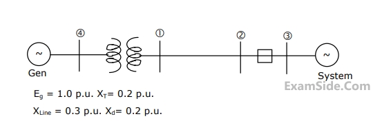
$$1.0$$ p.u. and $${Z_1} = {Z_2} = j0.1\,\,$$ p.u.,
$$\,{Z_0} = j0.05\,\,\,\,\,$$ p.u., for the alternator, then the required inductive reacttance for neutral grounding is
58
For the configuration shown in figure, the breaker connecting a large system to bus $$2$$ is initially open. The system $$3$$-phase fault level at bus $$3$$ under this condition is not known. After closing the system breaker, the $$3$$-phase fault level at bus $$1$$ was found to be $$5.0$$ p.u. What will be the new $$3$$-phase fault level at system bus $$3,$$ after the interconnection? All per unit values are on common base. Prefault load currents are neglected and prefault voltages are assumed to be $$1.0$$ p.u. at all buses. GATE EE 2000 Power System Analysis - Symmetrical Components and Symmetrical and Unsymmetrical Faults Question 7 English
59
In an inverse definite minimum time, electromagnetic type over-current relay, the minimum time feature is achieved because of
60
In a 3-step distance protection, the reach of the three zones of the relay at the beginning of the first line typically extends upto
61
The plug setting of a negative sequence relay is $$0.2$$ $$A.$$ The current transformer ratio is $$5:1$$. The minimum value of line to line fault current for the operation of the relay is
62
In a thermal power plant, the feed water coming to the economiser is heated using
63
Out of the considerations (i) to (iv) listed below,
(i) No distance limitation related to steady state stability
(ii) No reactive power requirement from the system at the two terminals
(iii) No substantial effect on fault level of the two systems at the terminals inspite of the inter connection
(iv) no corona problems
The considerations which constitute advantages of HVDC transmission are
EXAM MAP
Medical
NEETAIIMS
Graduate Aptitude Test in Engineering
GATE CSEGATE ECEGATE EEGATE MEGATE CEGATE PIGATE IN
Civil Services
UPSC Civil Service
Defence
NDA
Staff Selection Commission
SSC CGL Tier I
CBSE
Class 12