GATE EE


The network is used as a feedback circuit in an oscillator circuit shown in figure $$(2)$$ to generate sinusoidal oscillations. Assuming that the operational amplifier is ideal, determine the value of $${R_F}$$ for generating these oscillations. Also determine the oscillation frequency if $$R = 10\,\,k\Omega $$ and $$C=100PF$$

(a) Current through $${R_1}$$ and $${R_C}$$
(b) The output voltage $${V_0}$$
(c) The value of $${R_F}$$


$$(a)$$ Create a table of $${Q_0},{Q_1},{Q_2}$$ and $$A$$ in the format given below for $$10$$ successive
$$\,\,\,\,\,\,\,\,$$ input cycles of the clock $$CLK1.$$
$$(b)$$ Determine the module number of the counter.
$$(c)$$ Modify the circuit of Fig. to create a modulo$$-6$$ counter using the same
$$\,\,\,\,\,\,\,$$ components used in the figure.


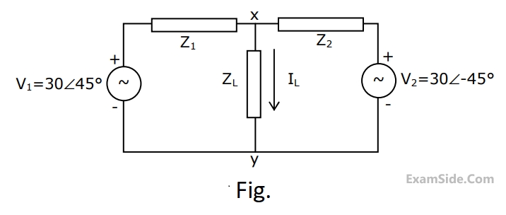
$${Z_1} = \left( {1 - j} \right)\Omega ,\,\,{Z_2} = \left( {1 + j} \right)\Omega $$ and $${Z_L} = \left( {1 + j0} \right)\Omega .$$ Obtain the Thevenin equivalent circuit (Thevenin voltage and impedance) across terminals $$X$$ and $$Y$$, and determine the current $${{\rm I}_L}$$ through the load $${Z_L}.$$


$$\eqalign{ & {{\rm I}_1} = {Y_{11}}\,\,{E_1} + {Y_{12}}\,\,{E_2} \cr & {{\rm I}_2} = {Y_{21}}\,\,{E_1} + {Y_{22}}\,\,{E_2} \cr} $$

The admittance parameters, $${Y_{11}},\,\,{Y_{12}},\,\,{Y_{21}}$$ and $${Y_{22}}$$ for the network shown are


$$(a)$$ the per phase open circuit voltage $${E_0}$$
$$(b)$$ the developed power for the new operating condition and corresponding power factor.


(a) The on-time $${t_{ON}}$$ of the switch
(b) The value of the peak current $${{\rm I}_p}$$


Fig. $$(b).$$ What is the rms value of the pole-to-pole voltage $${V_{12}}$$:


$$R = 50\Omega .$$ The source voltage is
$$V = 200sin\omega t,$$
Where $$\omega = 2\pi \times 50$$ radians per second. The power dissipated in the load resistor $$R$$ is

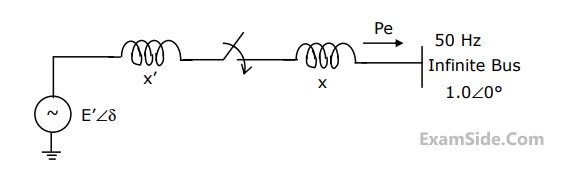
X1 = 0.1 pu, E1 = 1.0 pu, H = 5 MJ/MVA, mechanical power Pm = 0.0 pu, $$\omega $$B = 2 $$\pi \times $$50 rad/sec. All quantities are expressed on a common base.
The generator is initially running on open circuit with the frequency of the open circuit voltage slightly higher than that of the infinite bus. If at the instant of switch closure $$\delta = 0$$ and $$\omega = {{d\delta } \over {dt}} = {\omega _{init}},$$ compute the maximum value of $${\omega _{init}}$$ so that the generator pulls into synchronism.
$$\int {\left( {{{2H} \over {{\omega _B}}}} \right)\omega d\omega + {P_e}d\delta = 0} $$

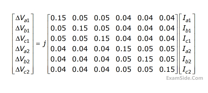
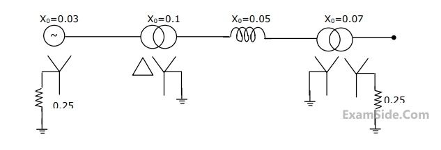
Compute the self and mutual zero sequence impedances of this system i.e, compute $${Z_{011}},\,\,{Z_{012}},\,\,{Z_{021}},\,\,{Z_{022}}\,\,\,$$ in the following equations.
$$\Delta {V_{01}} = {Z_{011}}\,{{\rm I}_{01}} + {Z_{012}}\,{{\rm I}_{02}}$$
$$\Delta {V_{02}} = {Z_{021}}\,{{\rm I}_{01}} + {Z_{022}}\,{{\rm I}_{02}}\,\,$$ where $$\,\Delta {V_{01}},$$
$$\Delta {V_{02}},\,{{\rm I}_{01}},\,{{\rm I}_{02}}\,\,$$ are the zero sequence voltage drops and currents for the two lines respectively.

and Zone $$2$$ settings for both the relays are indicated on the diagram. Which of the following indicates the correct time setting for the Zone $$2$$ of relays $$R1$$ and $$R2.$$
Characteristic impedance $${Z_c} = 400\Omega ,\,\,$$, propagation constant $$\,\beta = 1.2 \times {10^{ - 3}}\,\,rad/km,\,\,$$ and length $$\,l = 100\,km.\,\,$$ The equation relating sending and receiving end questions is $${V_s} = {V_r}\,\cosh \,\,\left( {\beta l} \right) + j\,Z{}_c\,\,\sinh \left( {\beta l} \right){{\rm I}_R}$$ Complete the maximum power that can be transferred to the UPF load at the receiving end if $$\left| {{V_s}} \right| = 230\,\,kV.\,\,$$


For the above system find an input $$u(t),$$ with zero initial condition, that produces the same output as with no input and with the initial conditions.
$${{d\,y\left( {{0^ - }} \right)} \over {dt}} = - 4,\,\,\,y\left( {{0^ - }} \right) = 1$$
