GATE EE 2014 Set 1
View Questions

GATE EE

1
The figure shows the circuit of a rectifier fed from a 230 V (rms), 50Hz sinusoidal voltage source. If we want to replace the current source with a resistor so that the rms value of the current supplied by the voltage source remains unchanged, the value of the resistance (in ohms) is __________ (Assume diodes to be ideal) GATE EE 2014 Set 1 Analog Electronics - Diode Circuits and Applications Question 24 English
2
The magnitude of the mid-band voltage gain of the circuit shown in figure is (assuming $${h_{fe}}$$ of the transistor to be $$100$$) GATE EE 2014 Set 1 Analog Electronics - Bjt and Mosfet Biasing Question 28 English
3
Given the Op-amps in the figure of ideal, the output voltage $${V_0}$$ is GATE EE 2014 Set 1 Analog Electronics - Operational Amplifier Question 23 English
4
In the figure shown, assume the op-amp to be ideal. Which of the alternatives gives the correct Bode plots for the transfer function $${{{V_O}\left( \omega \right)} \over {{V_i}\left( \omega \right)}}?$$ GATE EE 2014 Set 1 Analog Electronics - Operational Amplifier Question 22 English
5
In the Wien Bridge oscillator circuit shown in figure, the bridge is balanced when GATE EE 2014 Set 1 Analog Electronics - Feedback Amplifiers and Oscillator Circuits Question 8 English
6
In the formation of Routh-Hurwitz array for a polynomial, all the elements of a row have zero values. This premature termination of the array indicates the presence of
7
For the given system, it is desired that the system be stable. The minimum value of $$\alpha $$ for this condition is _________ GATE EE 2014 Set 1 Control Systems - Routh Hurwitz Stability Question 10 English
8
The root locus of unity feedback system is shown in figure GATE EE 2014 Set 1 Control Systems - Root Locus Techniques Question 14 English

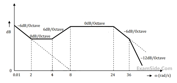
The closed loop transfer function of the system is

9
The Bode magnitude plot of the transfer function $$G\left( s \right) = {{K\left( {1 + 0.5s} \right)\left( {1 + as} \right)} \over {s\left( {1 + {s \over 8}} \right)\left( {1 + bs} \right)\left( {1 + {s \over {36}}} \right)}}$$ is shown below: Note that $$-6$$ $$dB/octave=-20$$ $$dB/decade.$$ The value of $${a \over {bK}}$$ is _______. GATE EE 2014 Set 1 Control Systems - Polar Nyquist and Bode Plot Question 24 English
10
Which of the following logic circuits is a realization of the function $$F$$ whose karnaugh map is shown in figure GATE EE 2014 Set 1 Digital Electronics - Minimization Question 3 English
11
A cascade of three identical modulo -$$5$$ counters has an over all modulus of
12
An output device is interfaced with $$8$$ bit microprocessor $$8085$$$$A.$$ The interfacing circuit is shown in figure GATE EE 2014 Set 1 Digital Electronics - Microprocessor Question 5 English

The interfacing circuit makes use of $$3$$ line to $$8$$ line decoder having $$3$$ enable lines $${E_1}\,\,\overline E {}_2,$$ $$\,\overline E {}_3$$. The address of the device is

13
The three circuit elements shown in the figure are part of an electric circuit. The total power absorbed by the three circuit elements in watts is ________________. GATE EE 2014 Set 1 Electric Circuits - Network Elements Question 49 English
14
In the figure, the value of resistor R is $$\left(25+\frac{\mathrm I}2\right)\mathrm\Omega$$, where I is the current in amperes. The current I is _____. GATE EE 2014 Set 1 Electric Circuits - Network Elements Question 41 English
15
An incandescent lamp is marked 40W, 240V. If resistance at room temperature $$\left(26^\circ\mathrm C\right)\;\mathrm{is}\;120\mathrm\Omega$$ and temperature coefficient of resistance is $$4.5\;\times\;10^{-3}/^\circ C$$ , then its ‘ON’ state filament temperature in oC is approximately ________.
16
A combination of 1μF capacitor with an initial voltage Vc(0) = −2V in series with a 100Ω resistor is connected to a 20 mA ideal dc current source by operating both switches at t = 0s as shown. Which of the following graphs shown in the options approximates the voltage Vs across the current source over the next few seconds? GATE EE 2014 Set 1 Electric Circuits - Transient Response Question 32 English
17
C0 is the capacitance of a parallel plate capacitor with air as dielectric (as in figure (a)). If, half of the entire gap as shown in figure (b) is filled with a dielectric of permittivity $$\in_r$$ , the expression for the modified capacitance is GATE EE 2014 Set 1 Electric Circuits - Network Elements Question 50 English
18
The reading of voltmeter $$(rms)$$ in volts, for the circuit shown in the figure is ______. GATE EE 2014 Set 1 Electrical and Electronics Measurement - Basic of Indicating Instruments Question 10 English
19
The dc current flowing in a circuit is measured by two ammeters, one PMMC and another electrodynamometer type, connected in series. The PMMC meter contains 100 turns in the coil, the flux density in the air gap is 0.2 Wb/m2 , and the area of the coil is 80 mm2. The electrodynamometer ammeter has a change in mutual inductance with respect to deflection of 0.5 mH/deg. The spring constants of both the meters are equal. The value of current, it which the deflection of the two meters are same, is ___________.
20
Power consumed by a balanced $$3$$-phase, $$3$$-wire load is measured by the two wattmeter method. The first wattmeter reads twice that of the second. Then the load impedance angle in radians is
21
In an oscilloscope screen, linear sweep is applied at the
22
A three phase synchronous generator is to be connected to the infinite bus. The lamps are connected as shown in the figure for the synchronization. The phase sequence of bus voltage is $$R$$-$$Y$$-$$B$$ and that of incoming generator voltage is $$R'$$ - $$Y'$$ - $$B'.$$ GATE EE 2014 Set 1 Electrical Machines - Synchronous Machines Question 25 English

It was found that the lamps are becoming dark in the sequence $${L_a} - {L_b} - {L_c}.$$ It means that the phase sequence of incoming generator is

23
An 8-pole, 3-phase, 50 Hz induction motor is operating at a speed of 700 rpm. The frequency of the rotor current of the motor in Hz is ________.
24
A 15kW, 230V dc shunt motor has armature circuit resistance of 0.4 $$\Omega$$ and field circuit resistance of 230 $$\Omega$$. At no load and rated voltage, the motor runs at 1400 rpm and the line current drawn by the motor is 5 A. At full load, the motor draws a line current of 70 A. Neglect armature reaction. The full load speed of the motor in rpm is ________________
25
For a specified input voltage and frequency, if the equivalent radius of the core of a transformer is reduced by half, the factor by which the number of turns in the primary should change to maintain the same no load current is
26
The core loss of a single phase, 230/115 V, 50 Hz power transformer is measured from 230 V side by feeding the primary (230 V side) from a variable voltage variable frequency source while keeping the secondary open circuited. The core loss is measured to be 1050 W for 230 V, 50 Hz input. The core loss is again measured to be 500W for 138 V, 30 Hz input. The hysteresis and eddy current losses of the transformer for 230 V, 50 Hz input are respectively.
27
A 3 phase, 50 Hz, 6 pole induction motor has a rotor resistance of 0.1 Ω and reactance of 0.92 Ω. Neglect the voltage drop in stator and assume that the rotor resistance is constant. Given that the full load slip is 3%, the ratio of maximum torque to full load torque is
28
A star connected 400 V, 50 Hz, 4 pole synchronous machine gave the following open circuit and short circuit test results:
Open circuit test: VOC = 400 V (rms, line–to–line) at field current, If = 2.3 A
Short circuit test: ISC = 10 A(rms, phase) at field current, If =1.5 A
The value of per phase synchronous impedance in Ω at rated voltage is __________.
29
The following four vector fields are given in cartesian coordinate system. The vector field which does not satisfy the property of magnetic flux density is
30
Let $$S$$ be the set of points in the complex plane corresponding to the unit circle. $$\left( {i.e.,\,\,S = \left\{ {z:\left| z \right| = 1} \right\}} \right.$$ Consider the function $$f\left( z \right) = z{z^ * }$$ where $${z^ * }$$ denotes the complex conjugate of $$z.$$ The $$f(z)$$ maps $$S$$ to which one of the following in the complex plane?
31
Let $$X\left( s \right) = {{3s + 5} \over {{s^2} + 10s + 20}}$$ be the Laplace Transform of a signal $$x(t).$$
Then $$\,x\left( {{0^ + }} \right)$$ is
32
Given a system of equations $$$x + 2y + 2z = {b_1}$$$ $$$5x + y + 3z = {b_2}$$$
Which of the following is true its solutions
33
A system matrix is given as follows $$$A = \left[ {\matrix{ 0 & 1 & { - 1} \cr { - 6} & { - 11} & 6 \cr { - 6} & { - 11} & 5 \cr } } \right].$$$

The absolute value of the ratio of the maximum eigenvalue to the minimum eigenvalue is ___________.

34
Let $$f\left( x \right) = x{e^{ - x}}.$$ The maximum value of the function in the interval $$\left( {0,\infty } \right)$$ is
35
The line integral of function $$F=yzi,$$ in the counterclockwise direction, along the circle $${x^2} + {y^2} = 1$$ at $$z=1$$ is
36
A fair coin is tossed $$n$$ times. The probability that the difference between the number of heads and tails is $$(n-3)$$ is
37
The solution for the differential equation $$\,\,{{{d^2}x} \over {d{t^2}}} = - 9x,\,\,$$ with initial conditions $$x(0)=1$$ and $${{{\left. {\,\,\,\,{{dx} \over {dt}}} \right|}_{t = 0}} = 1,\,\,}$$ is
38
Figure shows four electronic switches $$(i), (ii), (iii)$$ and $$(iv).$$ Which of the switches can block voltages of either polarity (applied between terminals $$‘a’$$ and $$‘b’$$) when the active device is in the OFF state? GATE EE 2014 Set 1 Power Electronics - Power Semiconductor Devices Question 16 English
39
The figure shows the circuit diagram of a rectifier. The load consists of a resistance $$10\,\Omega $$ and an inductance $$0.05$$ $$H$$ connected in series. Assuming ideal thyristor and ideal diode, the thyristor firing angle (in degree) needed to obtain an average load voltage of $$70$$ $$V$$ is _______________. GATE EE 2014 Set 1 Power Electronics - Single and Three Phase Rectifier Question 27 English
40
Figure (i) shows the circuit diagram of a chopper. The switch $$S$$ in the circuit in figure (i) is switched such that the voltage $${V_D}$$ across the diagram as the wave shape as shown in figure (ii). The capacitance $$C$$ is large so that the voltage across it is constant. If switch $$S$$ and the diode are ideal, the peak to peak ripple (in A) in the inductor current is ________. GATE EE 2014 Set 1 Power Electronics - Choppers and Commutation Techniques Question 23 English
41
In the figure shows on period of the output voltage of an inverter. $$\alpha $$ should be chosen such that $${60^0} < \alpha < {90^0}.$$ If $$rms$$ value of the fundamental component is $$50$$ $$V$$, then $$\alpha $$ in degree is _________. GATE EE 2014 Set 1 Power Electronics - Inverters Question 10 English
42
In an unbalanced three phase system phase current $${{\rm I}_a} = 1\angle \left( { - {{90}^0}} \right)\,\,pu,\,\,$$ negative sequence current $$\,{{\rm I}_{b2}} = 4\angle \left( { - {{150}^0}} \right)\,\,pu,\,\,$$ zero sequence current $$\,\,{{\rm I}_{c0}} = 3\angle {90^0}\,\,pu.\,\,\,$$ The magnitude of phase current $${{\rm I}_b}$$ in $$pu$ is
43
The fuel cost functions of two power plants are
Plant $${P_1}:\,{C_1} = 0.05\,Pg_1^2 + AP{g_1} + B$$
Plant $${P_2}:\,{C_2} = 0.10\,Pg_2^2 + 3AP{g_2} + 2B$$
Where, $$P{g_1}$$ and $$P{g_2}$$ are the generator powers of two plants and $$A$$ and $$B$$ are the constants. If the two plants optimally share $$1000$$ $$MW$$ load at incremental fuel cost of $$100$$ $$Rs/MWh,$$ the ratio of load shared by plants $${P_1}$$ and $${P_2}$$ is
44
The over current relays for the line protection and loads connected at the buses are shown in the figure. GATE EE 2014 Set 1 Power System Analysis - Switch Gear and Protection Question 7 English

The relays are IDMT is natural having the characteristic
$${t_{op}} = {{0.14\, \times \,time\,\,multiplier\,\,setting} \over {{{(plug\,\,setting\,\,multiplier)}^{0.02}} - 1}}$$
The maximum and minimum fault current at bus $$B$$ are $$2000A$$ and $$500$$ $$A$$ respectively. Assuming the time multiplier setting and plug setting for relay $${R_B}$$ to be $$0.1$$ and $$5$$ $$A$$ respectively, the operating time of $${R_B}$$ (in seconds) is __________.

45
A 2-bus system and corresponding zero sequence network are shown in the figure. GATE EE 2014 Set 1 Power System Analysis - Symmetrical Components and Symmetrical and Unsymmetrical Faults Question 36 English

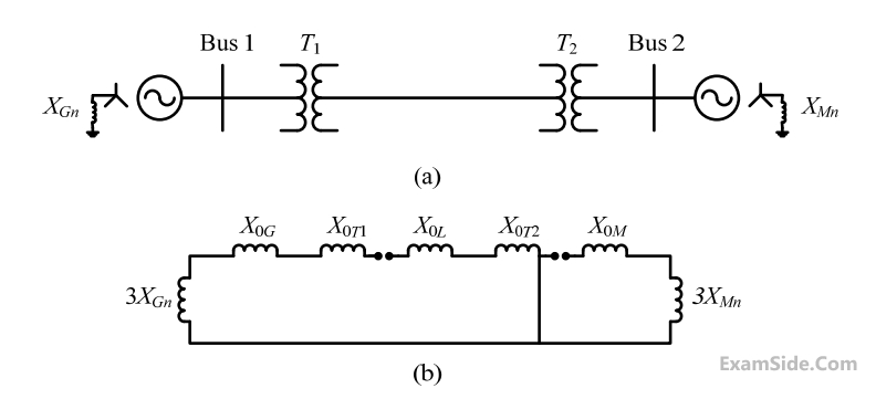
The transformers T1 and T2 are connected as

46
The undesirable property of an electrical insulating material is
47
A distribution feeder of $$1$$ $$km$$ length having resistance, but negligible reactance, is fed from both the ends by $$400$$ $$V,$$ $$50$$ $$Hz$$ balanced sources. Both voltage sources $${S_1}$$ and $${S_2}$$ are in phase. The feeder supplies concentrated loads of unity power factor as shown in the figure. GATE EE 2014 Set 1 Power System Analysis - Parameters and Performance of Transmission Lines Question 27 English

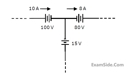
The contributions of $${S_1}$$ and $${S_2}$$ in $$100$$ $$A$$ current supplied at location $$P$$ respectively, are

48
A two bus power system shown in figure supplies load of $$1.0+j0.5$$ $$p.u$$ GATE EE 2014 Set 1 Power System Analysis - Parameters and Performance of Transmission Lines Question 26 English

The value of $${V_1}$$ in $$p.u$$ and $${\delta _2}$$ respectively are

49
Three phase to ground fault takes place at locations $${F_1}$$ and $${F_2}$$ in the system shown in the figure. GATE EE 2014 Set 1 Power System Analysis - Symmetrical Components and Symmetrical and Unsymmetrical Faults Question 37 English

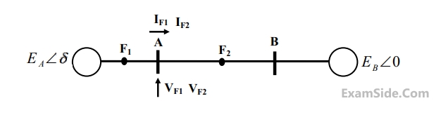
If the fault takes place at location $${F_1}$$, then the voltage and the current at bus A are $${V_F1}$$ and $${{\rm I}_{F1}}$$ respectively. If the fault takes place at location $${F_2}$$, then the voltage and the current at bus A are $${V_{F2}}$$ and $${{\rm I}_{F2}}$$ respectively.

The correct statement about voltages and currents during faults at $${F_1}$$ and $${F_2}$$ is

50
x(t) is nonzero only for $$T_x\;<\;t\;<\;T_x^1$$ , and similarly, y(t) is nonzero only for $$T_y\;<\;t\;<\;T_y^1$$ . Let z(t) be convolution of x(t) and y(t). Which one of the following statements is TRUE?
51
The function shown in the figure can be represented as GATE EE 2014 Set 1 Signals and Systems - Continuous and Discrete Time Signals Question 5 English
52
For a periodic square wave, which one of the following statements is TRUE?
53
Let f(t) be a continuous time signal and let F($$\omega$$) be its Fourier Transform defined by $$F\left(\omega\right)=\int_{-\infty}^\infty f\left(t\right)e^{-j\omega t}dt$$. Define g(t) by $$g\left(t\right)=\int_{-\infty}^\infty F\left(u\right)e^{-jut}du$$. What is the relationship between f(t) and g(t)?
54
Let $$X\left(z\right)=\frac1{1-z^{-3}}$$ be the Z–transform of a causal signal x[n]. Then, the values of x[2] and x[3] are
EXAM MAP
Medical
NEETAIIMS
Graduate Aptitude Test in Engineering
GATE CSEGATE ECEGATE EEGATE MEGATE CEGATE PIGATE IN
Civil Services
UPSC Civil Service
Defence
NDA
Staff Selection Commission
SSC CGL Tier I
CBSE
Class 12