GATE EE 2009
View Questions

GATE EE

1
The following circuit has $$R = 10k\Omega ,\,C = 10\mu F.$$ The input voltage is a sinusoidal at $$50HZ$$ with an $$RMS$$ values of $$10V.$$ Under ideal conditions, the current $${{\rm I}_S}$$ from the source is GATE EE 2009 Analog Electronics - Operational Amplifier Question 7 English
2
An ideal op-amp circuit and its input waveform are shown in the figures. The $$o/p$$ wave form of this circuit will be GATE EE 2009 Analog Electronics - Operational Amplifier Question 6 English 1 GATE EE 2009 Analog Electronics - Operational Amplifier Question 6 English 2
3
The following circuit has a voltage source $${V_s}$$ as shown in the graph. The current through the circuit is also shown GATE EE 2009 Analog Electronics - Diode Circuits and Applications Question 9 English 1 GATE EE 2009 Analog Electronics - Diode Circuits and Applications Question 9 English 2 GATE EE 2009 Analog Electronics - Diode Circuits and Applications Question 9 English 3

The element connected between $$' a '$$ and $$' b '$$ could be

4
The nature of feedback in the op-amp circuit shown is GATE EE 2009 Analog Electronics - Operational Amplifier Question 48 English
5
A system is described by the following state and output equations $$${{d{x_1}\left( t \right)} \over {dt}} = - 3{x_1}\left( t \right) + {x_2}\left( t \right) + 2u\left( t \right)$$$ $$${{d{x_2}\left( t \right)} \over {dt}} = - 2{x_2}\left( t \right) + u\left( t \right)$$$

$$y\left( t \right) = {x_1}\left( t \right)$$ when $$u(t)$$ is the input and $$y(t)$$ is the output

The state $$-$$ transition matrix of the above system is

6
Errors associated with each respective subsystem $$\,{G_1},\,{G_2}$$ and $${G_3}$$ are $${\varepsilon _1},\,\,{\varepsilon _2}$$ and $${\varepsilon _3}$$. The error associated with the output is : GATE EE 2009 Control Systems - Basics of Control System Question 1 English
7
The first two rows of Routh's tabulation of a third order equation are as follows $$$\left. {\matrix{ {{s^3}} \cr {{s^2}} \cr } } \right|\matrix{ 2 & 2 \cr 4 & 4 \cr } $$$
this means there are

8
The unit - step response of a unity feedback system with open loop transfer function $$G\left( s \right) = {K \over {\left( {s + 1} \right)\left( {s + 2} \right)}}$$ is shown in the figure. The value of $$K$$ is GATE EE 2009 Control Systems - Time Response Analysis Question 8 English
9
The open loop transfer function of a unity feedback system is given by $$G\left( s \right) = \left( {{e^{ - 0.1s}}} \right)/s.$$
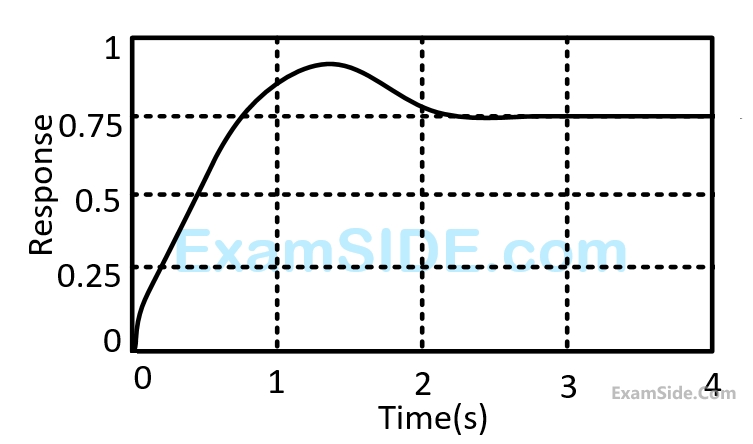
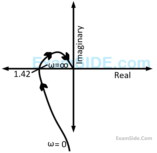
The gain margin of this system is
10
The polar plot of an open loop stable system is shown below. The closed loop systems is GATE EE 2009 Control Systems - Polar Nyquist and Bode Plot Question 14 English
11
The asymptotic approximation of the log magnitude vs frequency plot of a system containing only real poles and zeros is shown. Its transfer function is GATE EE 2009 Control Systems - Polar Nyquist and Bode Plot Question 9 English
12
A system is described by the following state and output equations $$${{d{x_1}\left( t \right)} \over {dt}} = - 3{x_1}\left( t \right) + {x_2}\left( t \right) + 2u\left( t \right)$$$ $$${{d{x_2}\left( t \right)} \over {dt}} = - 2{x_2}\left( t \right) + u\left( t \right)$$$

$$y\left( t \right) = {x_1}\left( t \right)$$ when $$u(t)$$ is the input and $$y(t)$$ is the output

The system transfer function is

13
The complete set of only those Logic Gates designated as Universal gates is
14
In $$8085$$ microprocessor, the contents of the Accumulator, after the following instructions are executed will become

$$\eqalign{ & XRA\,\,\,A \cr & MVI\,\,\,B\,\,\,F0\,\,\,H \cr & SUB\,\,\,B \cr} $$

15
For the circuit shown, find out the current flowing through the $$2\Omega $$ resistance. Also identify the changes to be made to double the current through the $$2\Omega $$ resistance. GATE EE 2009 Electric Circuits - Network Elements Question 6 English
16
The current through the $$2\,\,k\Omega $$ resistance in the circuit shown in Fig. is GATE EE 2009 Electric Circuits - Network Elements Question 15 English
17
The equivalent capacitance of the input loop of the circuit shown in below GATE EE 2009 Electric Circuits - Network Elements Question 7 English
18
GATE EE 2009 Electric Circuits - Network Theorems Question 11 English

For the circuit given above, the Thevenin's resistance across the terminals $$A$$ and $$B$$ is

19
GATE EE 2009 Electric Circuits - Network Theorems Question 10 English

For the circuit given above, the Thevenin's voltage across the terminals $$A$$ and $$B$$ is

20
In the Fig. shown, all elements used are ideal. For time t<0, S1 remained closed and S2 open. At t=0, S1 is opened and S2 is closed.If the voltage VC2 across the capacitor C2 at t = 0 is zero, the voltage across the capacitor combiation at t = 0+ will be GATE EE 2009 Electric Circuits - Transient Response Question 28 English
21
How many 200 W/200 V incandescent lamps connected in series would consume the same total power as a single 100 W/200 V incandescent lamp?
22
An average-reading digital multimeter reads $$10V$$ when fed with a triangular wave, symmetric about the time axis. For the same input an rms reading meter will read.
23
The figure shows a three phase delta connected load supplied from a $$400V,$$ $$50Hz,$$ $$3\phi $$ balanced source. The pressure coil and current coil of a wattmeter are connected to the load as shown. With the coil polarities suitably selected to ensure a positive deflection. The wattmeter reading will be. GATE EE 2009 Electrical and Electronics Measurement - Measurement of Energy and Power Question 3 English
24
The two inputs of a $$CRO$$ are fed with two stationary periodic signals. In the $$X$$-$$Y$$ mode, the screen shows a figure which changes from ellipse to circle and back to ellipse with its major axis changing orientation slowly and repeatedly. The following inference can be made from this.
25
A $$200$$ $$V,$$ $$50$$ $$Hz,$$ single-phase induction motor has the following connection diagram and winding orientations shown. $$MM'$$ is the axis of the main stator winding $$\left( {{M_1}{M_2}} \right)$$ and $$AA'$$ is that of the auxiliary winding $$\left( {{A_1}{A_2}} \right).$$ Directions of the winding axis indicate direction of flux when currents in the windings are in the directions shown. Parameters of each winding are indicated. When switch $$S$$ is closed, the motor GATE EE 2009 Electrical Machines - Induction Machines Question 10 English
26
A field excitation of $$20A$$ in a certain alternator results in a armature current of $$400$$ $$A$$ in short circuit and a terminal voltage of $$2000$$ $$V$$ on open circuit. The magnitude of the internal voltage drop with in the machine at a load current of $$200$$ $$A.$$
27
Figure shows the extended view of a $$2$$ pole $$dc$$ machine with $$10$$ armature conductors. Normal brush positions are shown by $$A$$ and $$B,$$ placed at the inter polar axis. If the brushes are now shifted, in the direction of rotation to $$A'$$ and $$B'$$ as shown, the voltage waveform $${V_{A'B'}}$$ will resemble GATE EE 2009 Electrical Machines - D.C Machines Question 8 English
28
The single phase, $$50$$ $$Hz$$ iron core transformer in the circuit has both the vertical arms of cross sectional area $$20\,\,c{m^2}$$ and both the horizontal arms of cross sectional area $$10\,\,c{m^2}$$. If the two windings shown were wound instead on opposite horizontal arms, the mutual inductances will GATE EE 2009 Electrical Machines - Transformers Question 30 English
29
GATE EE 2009 Electrical Machines - Transformers Question 21 English

The figure above shows coil $$1$$ and $$2,$$ with dot markings as shown, having $$4000$$ and $$6000$$ turns respectively. Both the coils have a rated current of $$25$$ $$A.$$ Coil $$1$$ is excited with single phase, $$400$$ $$V,$$ $$50$$ $$Hz$$ supply.

In the auto-transformer obtained in Question $$30,$$ the current in each coil is

30
GATE EE 2009 Electrical Machines - Transformers Question 22 English

The figure above shows coil $$1$$ and $$2,$$ with dot markings as shown, having $$4000$$ and $$6000$$ turns respectively. Both the coils have a rated current of $$25$$ $$A.$$ Coil $$1$$ is excited with single phase, $$400$$ $$V,$$ $$50$$ $$Hz$$ supply.

The coils are to be connected to obtain a single-phase, $${{400} \over {1000}}\,\,V,$$ auto-transformer to drive a load of $$10$$ $$kVA.$$ Which of the options given should be exercised to realize the required auto-transformer?

31
GATE EE 2009 Electrical Machines - Transformers Question 19 English

The star-delta transformer shown above is excited on the star side with balanced, $$4$$-wire, $$3$$-phase, sinusoidal voltage supply of rated magnitude. The transformer is under no load condition.

With both $$S1$$ and $$S2$$ open, the core flux waveform will be

32
GATE EE 2009 Electrical Machines - Transformers Question 18 English

The star-delta transformer shown above is excited on the star side with balanced, $$4$$-wire, $$3$$-phase, sinusoidal voltage supply of rated magnitude. The transformer is under no load condition.

With $$S2$$ closed and $$S1$$ open, the current waveform in the delta winding will be

33
The circuit diagram shows a two-winding, lossless transformer with no leakage flux, excited from a current source, $$i(t)$$, whose waveform is also shown. The transformer has a magnetizing inductance of $$400/\pi \,\,mH.$$ GATE EE 2009 Electrical Machines - Transformers Question 15 English 1 GATE EE 2009 Electrical Machines - Transformers Question 15 English 2

If the waveform of $$i\left( t \right) = 10\sin \left( {100\pi t} \right)A,$$ the peak voltage across $$A$$ and $$B$$ with $$S$$ closed is

34
The circuit diagram shows a two-winding, lossless transformer with no leakage flux, excited from a current source, $$i(t)$$, whose waveform is also shown. The transformer has a magnetizing inductance of $$400/\pi \,\,mH.$$ GATE EE 2009 Electrical Machines - Transformers Question 16 English 1 GATE EE 2009 Electrical Machines - Transformers Question 16 English 2

The peak voltage across $$A$$ and $$B$$, with $$S$$ open is

35
$$$F\left(x,y\right)=\left(x^2\;+\;xy\right)\;{\widehat a}_x\;+\;\left(y^2\;+\;xy\right)\;{\widehat a}_y$$$. Its line integral over the straight line from (x, y)=(0,2) to (2,0) evaluates to
36
The trace and determinant of a $$2 \times 2$$ matrix are shown to be $$-2$$ and $$-35$$ respectively. Its eigen values are
37
If $$(x, y)$$ is continuous function defined over $$\left( {x,y} \right) \in \left[ {0,1} \right] \times \left[ {0,1} \right].\,\,\,$$ Given two constants, $$\,x > {y^2}$$ and $$\,y > {x^2},$$ the volume under $$f(x, y)$$ is
38
$$F\left( {x,y} \right) = \left( {{x^2} + xy} \right)\,\widehat a{}_x + \left( {{y^2} + xy} \right)\,\widehat a{}_y.\,\,$$ Its line integral over the straight line from $$(x, y)=(0,2)$$ to $$(x,y)=(2,0)$$ evaluates to
39
Assume for simplicity that $$N$$ people, all born in April (a month of $$30$$ days) are collected in a room, consider the event of at least two people in the room being born on the same date of the month (even if in different years e.g. $$1980$$ and $$1985$$). What is the smallest $$N$$ so that the probability of this exceeds $$0.5$$ is ?
40
Let $$\,{x^2} - 117 = 0.\,\,$$ The iterative steps for the solution using Newton -Raphson's method is given by
41
An $$SCR$$ is considered to be a semi - controlled device because
42
Match the switch arrangements on the top row to be steady $$-$$ state $$V$$ - $$I$$ characteristics on the lower row. The steady state operating points are shown by large black dots. GATE EE 2009 Power Electronics - Power Semiconductor Devices Question 8 English 1 GATE EE 2009 Power Electronics - Power Semiconductor Devices Question 8 English 2
43
In the chopper circuit shown, the main thyristor $$\left( {{T_M}} \right)$$ is operated at a duty ratio of $$0.8$$ which is much larger than the commutation interval. If the maximum allowable reapplied $${{dV} \over {dt}}$$ on $${T_M}$$ is $$50$$ $$V/\mu s,$$
what should be the theoretical minimum value of $${C_1}?$$. Assume current ripple through $${L_0}$$ to be negligible. GATE EE 2009 Power Electronics - Choppers and Commutation Techniques Question 9 English
44
The Current Source Inverter shown in Figure is operated by alternately turning on thyristor pairs $$\left( {{T_1},\,\,{T_2}} \right)$$ and $$\left( {{T_3},\,\,{T_4}} \right).$$ If the load is purely resistive, the theoretical maximum output frequency obtainable will be GATE EE 2009 Power Electronics - Inverters Question 15 English
45
The circuit shows an ideal diode connected to a pure inductor and is connected to a purely sinusoidal $$50$$ $$Hz$$ voltage source. Under ideal condition the current waveform through the indicator will look like GATE EE 2009 Power Electronics - Single and Three Phase Rectifier Question 12 English
46
Out of the following plant categories
(i) Nuclear , (ii) Run-of-river, (iii) Pump Storage, (iv) Diesel
The base load power plants are
47
For a fixed value of complex power flow in a transmission line having a sending end voltage $$V$$, the real power loss will be proportional to
48
Match the items List-$${\rm I}$$ (To) with the items in List-$${\rm II}$$ (Use) and select the correct answer using the codes given below the lists.

List-$${\rm I}$$
$$A.$$ improve power factor
$$B.$$ reduce the current ripples
$$C.$$ increase the power flow in line
$$D$$ reduce the Ferranti effect

List-$${\rm II}$$
$$1.$$ shunt reactor
$$2.$$ shunt capacitor
$$3.$$ series capacitor
$$4.$$ series reactor

49
A $$500$$ $$MW,$$ $$21$$ $$kV,$$ $$50$$ $$Hz,$$ $$3$$-phase, $$2$$-pole synchronous generator having a rated $$p.f.=$$$$0.9,$$ has a moment of inertia $$\,\,27.5\,\, \times \,\,{10^3}\,\,kg\,\,{m^2}.\,\,$$ The inertia constant $$(H)$$ will be
50
Three generators are feeding a load of $$100$$ $$MW$$. The details of the generators Rating, Efficiency and Regulation are shown below GATE EE 2009 Power System Analysis - Power Generation Cost Question 10 English

In the event of increased load power demand, which of the following will happen?

51
Match the items in List-$$I$$ (Type of transmission line) with the items in List-$$II$$ (Type of distance relay preferred) and select the correct answer using the codes below the lists.

List-$$I$$
$$A.$$ Short Line
$$B.$$ Mesium Line
$$C.$$ Long Line

List-$$II$$
$$1.$$ Ohm Relay
$$2.$$ Reactance Relay
$$3.$$ Mho Relay

52
For the $${Y_{bus}}$$ matrix of a $$4$$-bus system given in per unit, the buses having shunt elements are $$${Y_{BUS}} = j\left[ {\matrix{ { - 5} & 2 & {2.5} & 0 \cr 2 & { - 10} & {2.5} & 4 \cr {2.5} & {2.5} & { - 9} & 4 \cr 0 & 4 & 4 & { - 8} \cr } } \right]$$$
53
A linear Time Invariant system with an impulse response $$h(t)$$ produces output $$y(t)$$ when input $$x(t)$$ is applied. When the input $$x\left( {t - \tau } \right)$$ is applied to a system with response $$h\left( {t - \tau } \right)$$, the output will be
54
The $$z$$$$-$$ transform of a signal $$x\left[ n \right]$$ is given by $$4{z^{ - 3}} + 3{z^{ - 1}} + 2 - 6{z^2} + 2{z^3}.$$ It is applied to a system, with a transfer function $$H\left( z \right) = 3{z^{ - 1}} - 2.$$ Let the output be $$y(n)$$. Which of the following is true?
55
The Fourier Series coefficients, of a periodic signal $$x\left( t \right),$$ expressed as $$x\left( t \right) = \sum {_{k = - \infty }^\infty {a_k}{e^{j2\pi kt/T}}} $$ are given by
$${a_{ - 2}} = 2 - j1;\,\,{a_{ - 1}} = 0.5 + j0.2;\,\,{a_0} = j2;$$
$${a_1} = 0.5 - j0.2;\,\,{a_2} = 2 + j1;\,\,$$ and
$${a_k} = 0;$$ for $$|k|\,\, > 2.$$

Which of the following is true?

56
A cascade of 3 Linear Time Invariant systems is casual and unstable. From this, we conclude that
EXAM MAP
Medical
NEETAIIMS
Graduate Aptitude Test in Engineering
GATE CSEGATE ECEGATE EEGATE MEGATE CEGATE PIGATE IN
Civil Services
UPSC Civil Service
Defence
NDA
Staff Selection Commission
SSC CGL Tier I
CBSE
Class 12