1
GATE EE 2007
MCQ (Single Correct Answer)
+2
-0.6
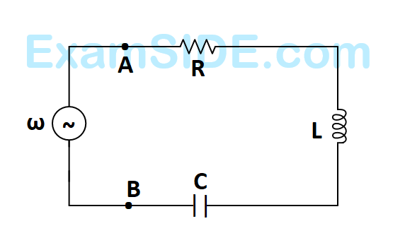
The $$R-L-C$$ series circuit shown is supplied from a variable frequency voltage source. The admittance $$-$$ locus of the $$R-L$$ $$-C$$ network at terminals $$AB$$ for increasing frequency $$\omega $$ is
A

B

C

D

2
GATE EE 2006
MCQ (Single Correct Answer)
+2
-0.6
The circuit shown in the figure is energized by a sinusoidal voltage source $${V_1}$$ at a frequency which causes resonance with a current of $${\rm I}$$.

The phasor diagram which is applicable to this circuit is
A

B

C

D

3
GATE EE 2005
MCQ (Single Correct Answer)
+2
-0.6
The $$RL$$ circuit of the figure is fed from a constant magnitude, variable frequency sinusoidal voltage source $${V_{IN.}}$$ At $$100Hz,$$ the $$R$$ and $$L$$ elements each have a voltage drop $${u_{RMS}}.$$ If the frequency of the source is changed to $$50Hz,$$ then new voltage drop across $$R$$ is

4
GATE EE 2004
MCQ (Single Correct Answer)
+2
-0.6
In Fig. the admittance values of the elements in Siemens are
$${Y_R} = 0.5 + j0,$$
$${Y_L} = 0 - j\,1.5,$$
$${Y_C} = 0 + j\,0.3$$ respectively.
The value of $${\rm I}$$ as a phasor when the voltage $$E$$ across the elements is $$10\angle {0^0}\,V$$ is
$${Y_R} = 0.5 + j0,$$
$${Y_L} = 0 - j\,1.5,$$
$${Y_C} = 0 + j\,0.3$$ respectively.
The value of $${\rm I}$$ as a phasor when the voltage $$E$$ across the elements is $$10\angle {0^0}\,V$$ is
GATE EE Subjects
Browse all chapters by subject
Electric Circuits
Electrical Machines
Engineering Mathematics
Signals and Systems
Power Electronics
Power System Analysis
Digital Electronics
Analog Electronics
Electromagnetic Fields
Control Systems
Electrical and Electronics Measurement
General Aptitude