GATE ECE 2001
GATE ECE
Assume that the OP_AMP in the figure, ideal
(a) Obtain an expression for V0 in terms of Vs, R, and the reverse satura
View Question The current gain of a BJT is
View Question An emitter-follower amplifier is shown in the figure, Zi is the impedance looking into the base of the transistor and Z0
View Question An npn BJT has gm = 38 mA/V, $${C_\mu }\, = {10^{ - 14}}$$ F, $${C_\pi }\, = 4\, \times {10^{ - 13}}\,F$$ and DC current
View Question The Oscillator circuit shown in the figure is
View Question The ideal Op-Amp has the following characteristics.
View Question Consider the following two statements.
Statement 1: Astable Multivibrator can be used for generating Square Wave.
St
View Question The Inverting Op-Amp shown in the figure, has an Open-loop gain of 100. The closed loop gain $${{{V_o}} \over {{V_s}}}$
View Question In the figure assume the Op-Amps to be ideal. The output V0 of the circuit is
View Question An Amplifier using an Op-Amp with a Slew-Rate SR = V/$$\mu $$sec, has a gain of 40 dB. If this amplifier has to faith f
View Question The PDF of a Gaussian random variable X is given by $${p_x}(x) = \,{1 \over {3\sqrt {2\pi } }}\,\exp \,[ - \,{(x - 4)^2}
View Question A band limited signal is sampled at the Nyquist rate. The signal can be recovered by passing the samples through
View Question During transmission over a communication channel, bit errors occur independently with probability 'p'. If a block of n b
View Question A video transmission system transmits 625 picture frames per second. Each frame consists of a $$400\,\, \times \,\,400$$
View Question The root-locus diagram for a closed loop feedback system is shown in Figure. The system is overdamped.
View Question A feedback control system is shown in figure
(a) Draw the signal-flow graph that represents the system.
(b) Find the to
View Question If the characteristic equation of a closed-loop system is s2 + 2s + 2 =0, then the
system is
View Question The equivalent of the block diagram in Figure is given as
View Question An electrical system and its signal-flow graph representations are shown in Figure
(a) and (b) respectively. The values
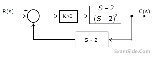
View Question The feedback control system in Figure is stable
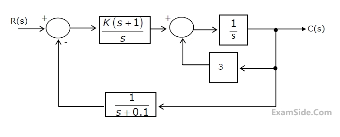
View Question Consider the feedback control system shown in figure.
(a) Find the transfer function of the system and its characterist
View Question Given the $$G\left(s\right)H\left(s\right)=\frac K{s\left(s+1\right)\left(s+3\right)}$$, the point of intersection of th
View Question The Nyquist plot for the open-loop transfer function G(s) of a unity negative
feedback system is shown in figure. if G(s
View Question The open-loop DC gain of a unity negative feedback system with closed-loop
transfer function $${{s + 4} \over {{s^2} + 7
View Question For the feedback control system shown in the figure, the process transfer function is
Gp(s) = $${1 \over {s(s + 1)}},$$
View Question In the figure the LED
View Question For the digital block shown in Figure. 2(a), the output Y=f(S3,S2,S1,S0) where S3
is MSB and S0 is LSB. Y is given in te
View Question The digital block in the figure is realized using two positive edge triggered D flip-flops. Assume that for t < t0, Q
View Question The 2’s complement representation of –17 is
View Question For the ring oscillator shown in the figure, the propagation delay of each inverter is 100 pico sec. What is the fundame
View Question In the TTL circuit in Figure 2.11, $${S_0}$$ to $${S_0}$$ are select lines and $${X_7}$$ and $${X_0}$$are input lines. $
View Question A transmission line is distortionless if
View Question If a plane electromagnetic wave satisfies the equation $${{{\partial ^2}\,{E_x}} \over {\partial \,{z^2}}} = \,{c^2}{{{\
View Question A uniform plane electromagnetic wave incident normally on a plane surface of a dielectric material is reflected with a V
View Question The phase velocity of waves propagating in a hollow metal waveguide is
View Question The dominant mode in a rectangular waveguide is $$T{E_{10}}$$, because this mode has
View Question A medium has breakdown strength of $$16$$ KV/m r.m.s. Its relative permeability is $$1.0$$ and relative permittivity is
View Question In a uniform linear array, four isotropic radiating elements are spaced $$\lambda /4$$ apart. The progressive phase shif
View Question A medium wave radio transmitter operating at a wavelength of 492 m has a tower antenna of height 124m. What is the radia
View Question A rectangular hollow metal waveguide has dimensions a = 2.29 cm and b = 1.02 cm. Microwave power at 10 GHz is transmitte
View Question A material has conductivity of 10-2 mho/m and a relative permittivity of 4. The
frequency at which the conduction curren
View Question MOSFET can be used as a
View Question Solve the differential equation $${{{d^2}y} \over {d{x^2}}} + y = x\,\,$$ with the following conditions $$(i)$$ at $$x=
View Question An 8085 microprocessor based system uses a 4K × 8-bit RAM whose starting
address is AA00H. The address of the last byte
View Question The circuit shown in Fig. is operating in steady-state with switch $${S_1}$$ closed. The switch $${S_1}$$ is opened at $
View Question When the angular frequency $$\omega $$ in Fig. is varied from $$0$$ to $$\infty $$ the locus of the current phasor $${{\
View Question If each branch of a Delta circuit has impedance $$\sqrt 3 \,Z$$, then each branch of the equivalent Wye circuit has impe
View Question The Z parameters $${Z_{11}}$$ and $${Z_{21}}$$ for the 2-port network in Fig. are
View Question The admittance parameters of a 2-port network shown in Fig. are given by $${Y_{11}} = \,2\,\,mho$$, $${Y_{12}}$$ = - 0.5
View Question The voltage e0 in figure is
View Question In figure, the value of the load resistor R which maximizes the power
delivered to it is
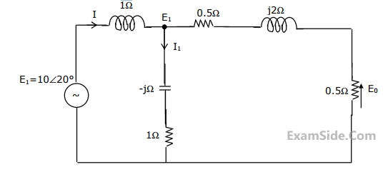
View Question For the circuit shown in the figure, determine the phasors E2, E0, I and I1.
View Question The admittance parameter Y12 in the 2-port network in Figure is
View Question The voltage e0 in Fig. is
View Question If a signal f(t) has energy E, the energy of the signal f(2t) is equal to
View Question The region of convergence of the z- transform of a unit step function is
View Question The transfer function of a system is given by $$H\left( s \right) = {1 \over {{s^2}\left( {s - 2} \right)}}$$. The impul
View Question The impulse response function of four linear system S1, S2, S3, S4 are given respectively by
$${h_1}$$(t), = 1;
$${h
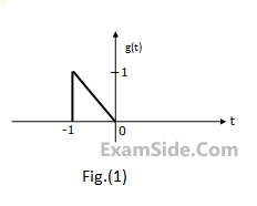
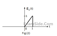
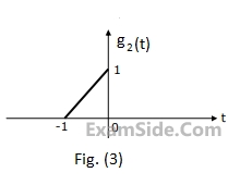
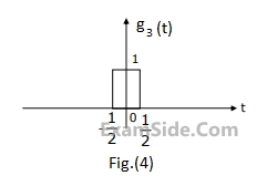
View Question The Fourier transform $$G(\omega )$$ of the signal g(t) in Fig.(1) is given as
$$G(\omega ) = {1 \over {{\omega ^2}}}({
View Question A band limited signal is sampled at the Nyquist rate. The signal can be recovered by passing the samples through
View Question A base band signal g(t) band limited to 100 Hz modulates a carrier of frequency $${{f_0}}$$ Hz. The modulated signal g(t
View Question The Nyquist sampling interval, for the signal Sinc(700t) + Sinc(500t) is
View Question Let $$\delta (t)$$ denote the delta function. The value of the the integral $$\int\limits_{ - \infty }^\infty {\delta (
View Question The PSD and the power of a signal g(t) are, respectively, Sg($$\omega$$) and Pg. The PSD
and the power of the signal ag(
View Question