1
GATE EE 2002
MCQ (Single Correct Answer)
+2
-0.6
In the single phase diode bridge rectifier shown in fig, the load resistor is
$$R = 50\Omega .$$ The source voltage is
$$V = 200sin\omega t,$$
Where $$\omega = 2\pi \times 50$$ radians per second. The power dissipated in the load resistor $$R$$ is GATE EE 2002 Power Electronics - Single and Three Phase Rectifier Question 41 English
A
$${{3200} \over \pi }W$$
B
$${{400} \over \pi }W$$
C
$$400\,W$$
D
$$800\,W$$
2
GATE EE 2002
MCQ (Single Correct Answer)
+2
-0.6
A three phase thyristor bridge rectifier is used in a $$HVDC$$ link. The firing angle $$\alpha $$ (as measured from the point of natural commutation) is constrained to lie between $${5^ \circ }$$ and $${30^ \circ }$$. If the $$dc$$ side current and $$ac$$ side voltage magnitude are constant, which of the following statements is true (neglect harmonics in the $$ac$$ side current and commutation overlap in your analysis)
A
Reactive power absorbed by the rectifier is maximum when $$\alpha = {5^ \circ }$$
B
Reactive power absorbed by the rectifier is maximum when $$\alpha = {30^ \circ }$$
C
Reactive power absorbed by the rectifier is maximum when $$\alpha = {15^ \circ }$$
D
Reactive power absorbed by the rectifier is maximum when $$\alpha = {15^ \circ }$$
3
GATE EE 2002
Subjective
+5
-0
A synchronous generator is to be connected to an infinite bus through a transmission line of reactance X = 0.2 pu, as shown in figure the generator data is as follows:

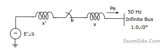
X1 = 0.1 pu, E1 = 1.0 pu, H = 5 MJ/MVA, mechanical power Pm = 0.0 pu, $$\omega $$B = 2 $$\pi \times $$50 rad/sec. All quantities are expressed on a common base.

The generator is initially running on open circuit with the frequency of the open circuit voltage slightly higher than that of the infinite bus. If at the instant of switch closure $$\delta = 0$$ and $$\omega = {{d\delta } \over {dt}} = {\omega _{init}},$$ compute the maximum value of $${\omega _{init}}$$ so that the generator pulls into synchronism.

$$\int {\left( {{{2H} \over {{\omega _B}}}} \right)\omega d\omega + {P_e}d\delta = 0} $$

GATE EE 2002 Power System Analysis - Power System Stability Question 6 English
4
GATE EE 2002
Subjective
+5
-0
Two transposed $$3$$ phase lines run parallel to each other. The equation describing the voltage drop in both lines is given below. GATE EE 2002 Power System Analysis - Load Flow Studies Question 10 English

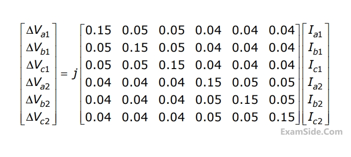
Compute the self and mutual zero sequence impedances of this system i.e, compute $${Z_{011}},\,\,{Z_{012}},\,\,{Z_{021}},\,\,{Z_{022}}\,\,\,$$ in the following equations.
$$\Delta {V_{01}} = {Z_{011}}\,{{\rm I}_{01}} + {Z_{012}}\,{{\rm I}_{02}}$$
$$\Delta {V_{02}} = {Z_{021}}\,{{\rm I}_{01}} + {Z_{022}}\,{{\rm I}_{02}}\,\,$$ where $$\,\Delta {V_{01}},$$
$$\Delta {V_{02}},\,{{\rm I}_{01}},\,{{\rm I}_{02}}\,\,$$ are the zero sequence voltage drops and currents for the two lines respectively.