GATE ECE 1993
View Questions

GATE ECE

Find the output voltage, V0 in the following circuit assuming that the Op-Amps are ideal.
View Question
The bandwidth of an n-stage tuned amplifier, with each stage having a band width of B, is given by
View Question
For the amplifier circuit of figure, the transistor has a $$\mathrm\beta$$ of 800. The mid-band voltage gain $$V_0/V_1$$
View Question
In a multi-stage RC-Coupled Amplifier the coupling capacitor.
View Question
Negative feedback in Amplifiers.
View Question
In a transistor push-pull Amplifier
View Question
For the ideal Op-Amp circuit of fig. Determine the output voltage V0
View Question
Which of the following demodulator(s) can be used for demodulating the signal $$x(t)\;=\;5\left(1+2\;\cos200\mathrm{πt}\
View Question
A superheterodyne radio receiver with an intermediate frequency of 455 KHz is tuned to a station operating at 1200 KHz.
View Question
If $$s^3+\;3s^2\;+\;4s\;+A\;=\;0$$ ,then all the roots of this equation are in the left half plane provided that
View Question
The truth table for the output Y in terms of three inputs A, B and C are given in table. Draw a logic circuit realizatio
View Question
Signals A,B,C,D and $$\overline D $$ are available. Using a single 8 - to - 1 multiplexer and no other gate, implement t
View Question
A pulse train with a frequency of 1 MHz is counted using a modulo-1024 ripple-counter built with J-K flip flops. For pro
View Question
2’s complement representation of a 16-bit number (one sign bit and 15 magnitude bits) is FFFI. Its magnitude in decimal
View Question
Boolean expression for the output of XNOR (equivalence) logic gate with inputs A and B is
View Question
For the logic circuit shown in Figure, the output is equal to
View Question
A material is described by the following electrical parameters at a frequency of $$10$$ GHz is $$\sigma = {10^6}$$ mho/
View Question
Consider a transmission line of characteristic impedance 50 ohm. Let it be terminated at one end by ( + j50) ohm. The VS
View Question
A plane wave is incident normally on a perfect conductor as shown in Fig. Here $$E_x^i,\,\,H_y^i$$ and $$\overrightarrow
View Question
Match the following descriptions with each of the diagrams given in Fig. Fields are near the interface, but on opposite
View Question
Consider an array of two non-directional radiators with spacing $$d\,\, = \,\,0.5\,\,\lambda $$. Determine the direction
View Question
An optical fiber consists of a cylindrical dielectric rod of refractive index $$n_1$$, surrounded by another dielectric
View Question
Given,$$\overrightarrow V=x\cos^2y\;\;\widehat{\mathrm i}\;+\;\mathrm x^2\mathrm e^\mathrm z\;\widehat{\mathrm j}\;+\;\m
View Question
The built-in potential (Diffusion Potential) in a p-n junction
View Question
If the linear velocity $${\overrightarrow V }$$ is given by $$\overrightarrow V = {x^2}y\overrightarrow i + xyz\overri
View Question
Given the differential equation $${y^1} = x - y$$ with initial condition $$y(0)=0.$$ The value of $$y(0.1)$$ calculated
View Question
In a microprocessor, the register which holds the address of the next instruction to be fetched is
View Question
In a microcomputer, wait states are used to
View Question
An infinite grid is built up by connecting resistors in the manner indicated in figure, where each branch represents one
View Question
In the following circuit the capacitance varies as C = KQ, where K is a constant equal to 0.5 Farads/Coulomb and Q, the
View Question
In figure, A1, A2 and A3 are ideal ammeters. If A1 reads 5 A, A2, A2 reads 12 A, then A3 should read
View Question
A network contains linear resistors and ideal voltage sources. If values of all the resistors are doubled, then the volt
View Question
The two electrical sub-network N1 and N2 are connected through three resistors as shown in figure. The voltage across
View Question
If the secondary winding of the ideal transformer shown in the circuit of the figure has 40 turns, the number of turns i
View Question
In the series circuit shown in figure, for series resonance, the value of the coupling coefficient K will be
View Question
In the circuit of figure, when switch S1 is closed, the ideal ammeter M1 reads 5A. What will be ideal voltmeter M2 rea
View Question
A dc circuit shown in figure has a voltage source V, a current source I and several resistors. A particular resistor R d
View Question
If $$F\left( s \right) = L\left[ {f\left( t \right)} \right] = {K \over {\left( {s + 1} \right)\,\left( {{s^2} +
View Question
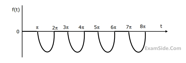
The Laplace transform of the periodioc function f(t) describe4d by the curve below, i.e., $$f\left( t \right) = \left\{
View Question
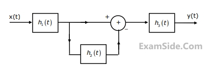
Consider the following interconnection of the three LTI systems (Fig.1). $${h_1}(t)$$ , $${h_2}(t)$$ and $${h_3}(t)$$ ar
View Question
Sketch the waveform (with properly marked axes) at the output of a matched filter matched for a signal s(t), of duration
View Question
Obtain an expression for the signal in figure, for the signal $${v_3}(t)$$ in Fig for $${v_1}(t) = 100\cos (2000\pi t)
View Question
A low pass signal m(t) band-limited to B Hz is sampled by a periodic rectangular pulse train, $${p_\tau }(t)$$ of period
View Question
EXAM MAP
Medical
NEETAIIMS
Graduate Aptitude Test in Engineering
GATE CSEGATE ECEGATE EEGATE MEGATE CEGATE PIGATE IN
Civil Services
UPSC Civil Service
Defence
NDA
Staff Selection Commission
SSC CGL Tier I
CBSE
Class 12