GATE EE


The Transconductance of the $$MOSFET$$ is
The voltage gain of the amplifier is


$$\mathop X\limits^ \bullet \left( t \right) = \left( {\matrix{ 0 & 1 \cr 0 & { - 3} \cr } } \right)X\left( t \right) + \left( {\matrix{ 1 \cr 0 \cr } } \right)u\left( t \right)$$ with the initial condition $$X\left( 0 \right) = {\left[ { - 1\,\,3} \right]^T}$$ and the unit step input $$u(t)$$ has
The state transition equation
$$\mathop X\limits^ \bullet \left( t \right) = \left( {\matrix{ 0 & 1 \cr 0 & { - 3} \cr } } \right)X\left( t \right) + \left( {\matrix{ 1 \cr 0 \cr } } \right)u\left( t \right)$$ with the initial condition $$X\left( 0 \right) = {\left[ { - 1\,\,3} \right]^T}$$ and the unit step input $$u(t)$$ has
The state transition matrix


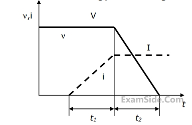
If, at $$t = {0^ + }$$, the voltage across the coil is $$120$$ $$V,$$ the value of resistance $$R$$ is

For the value of $$R$$ obtained in the above question, the time taken for $$95\% $$ of the stored energy to be dissipated is close to


The power angle is close to
The induced $$emf$$ is close to (line to line)
Assertion [a]: Under V/f control of induction motor, the maximum value of the developed torque remains constant over a wide range of speed in the subsynchronous region.
Reason [r]: The magnetic flux is maintained almost constant at the rated value by keeping the ratio V/f constant over the considered speed range.

Group-I(Performance variables)
(P) Armature emf (E)
(Q) Developed torque (T)
(R) Developed power (P)
Group-II(Proportional to)
1.Flux ($$\phi$$), speed ($$\omega$$) and armature current ($$I_a$$)
2.$$\phi$$ and $$\omega$$ only
3.$$\phi$$ and $$I_a$$ only
4.$$I_a$$ and $$\omega$$ only
5.$$I_a$$ only
(i) at half the rated speed by armature voltage control and
(ii) at 1.5 times the rated speed by field control, the respective output powers delivered by the motor are approximately


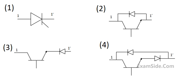
Which of the following are valid realizations of the switch $$s$$?
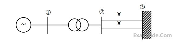
The positive sequence driving point reactance at the bus is
Inertia, M = $$20$$ p.u.; reactance X = $$2$$ p.u. The p.u. values of inertia and reactance on $$100$$ MVA common base, respectively are
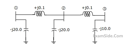
The zero sequence driving point reactance at the bus is
$${F_1} = a + b{P_1} + cP_1^2\,Rs/hour$$
$${F_2} = a + b{P_2} + 2cP_2^2\,Rs/hour$$
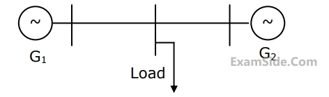
Where $${P_1}$$ and $${P_2}$$ are the generations in $$MW$$ of $${G_1}$$and $${G_2}$$, respectively. For most economic generation to meet $$300MW$$ of load $${P_1}$$ and $${P_2},$$ respectively, are
