1
GATE EE 2005
MCQ (Single Correct Answer)
+2
-0.6
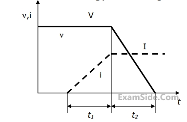
The figure shows the voltage across a power semiconductor device and the current through the device during a switching transition. Is the transition a turn ON transition or a turn OFF transition? What is the energy lost during the transition?
2
GATE EE 2005
MCQ (Single Correct Answer)
+1
-0.3
A three - phase diode bridge rectifier is fed from a $$400$$ $$V$$ $$RMS$$. $$50$$ $$Hz$$, three $$-$$ phase $$AC$$ source. If the load is purely resistive, then peak instantaneous output voltage is equal to
3
GATE EE 2005
MCQ (Single Correct Answer)
+2
-0.6
Consider a phase $$-$$ controlled converter shown in figure The thyristor is fired at an angle $$\alpha $$ in every positive half cycle of the input voltage. If the peak value of the instantaneous output voltage equals $$230$$ $$V,$$ the firing angle $$\alpha $$ is close to

4
GATE EE 2005
MCQ (Single Correct Answer)
+2
-0.6
At a $$220$$ kV substation of a power system, it is given that the three-phase fault level is $$4000$$ MVA and single-line to ground fault level is $$5000$$ MVA. Neglecting the resistance and the shunt susceptances of the system.
The zero sequence driving point reactance at the bus is
Paper Analysis
Total Questions
Analog Electronics 8
Control Systems 9
Digital Electronics 6
Electric Circuits 9
Electrical and Electronics Measurement 7
Electrical Machines 13
Engineering Mathematics 10
Power Electronics 7
Power System Analysis 10
Signals and Systems 6
More Papers of GATE EE
GATE EE 2026 GATE EE 2025 GATE EE 2024 GATE EE 2023 GATE EE 2022 GATE EE 2021 GATE EE 2020 GATE EE 2019 GATE EE 2018 GATE EE 2017 Set 2 GATE EE 2017 Set 1 GATE EE 2016 Set 1 GATE EE 2016 Set 2 GATE EE 2015 Set 1 GATE EE 2015 Set 2 GATE EE 2014 Set 3 GATE EE 2014 Set 2 GATE EE 2014 Set 1 GATE EE 2013 GATE EE 2012 GATE EE 2011 GATE EE 2010 GATE EE 2009 GATE EE 2008 GATE EE 2007 GATE EE 2006 GATE EE 2005 GATE EE 2004 GATE EE 2003 GATE EE 2002 GATE EE 2001 GATE EE 2000 GATE EE 1999 GATE EE 1998 GATE EE 1997 GATE EE 1996 GATE EE 1995 GATE EE 1994 GATE EE 1993 GATE EE 1992 GATE EE 1991
GATE EE Papers
All year-wise previous year question papers
2026
2025
2024
2023
2022
2021
2020
2019
2018
2013
2012
2011
2010
2009
2008
2007
2006
2005
2004
2003
2002
2001
2000
1999
1998
1997
1996
1995
1994
1993
1992
1991