GATE EE

Assuming forward voltage drops of the diodes to be $$0.7V,$$ the input-output transfer characteristics of the circuit is

If the forward voltage drop of diode is $$0.7V.$$ Then the current through collector will be

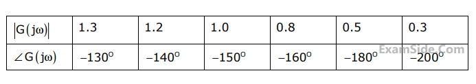
The gain margin and phase margin of the system are
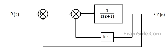
The gain $$k$$ of the Tacho-generator influences mainly the


It the state $${Q_A}{Q_B}$$ of the counter at the clock time $${t_n}$$ is $$'10'$$ then the state $${Q_A}{Q_B}$$ of the counter at $${t_n} + 3$$ (after three clock cycles) will be
$$\eqalign{ & LXI\,\,\,\,\,\,\,\,\,\,\,\,\,D\,\,\,DISP \cr & LP\,\,\,\,\,\,\,\,\,\,\,\,\,\,\,CALL\,\,\,SUB \cr} $$
It is desired that control be returned to $$LP+DISP+3$$ when the $$RET$$ instruction is executed in the subroutine. The set of instructions that precede the $$RET$$ instruction in the subroutine are

 The current $${\underline I}_C$$ in the figure above is
The power dissipated in the resistor R is
The current $${\underline I}_C$$ in the figure above is
The power dissipated in the resistor R is
(i) The compensating coil of a low power factor wattmeter compensates the effect of the impedance of the current coil.
(ii) The compensating coil of a low power factor wattmeter compensates the effect of the impedance of the voltage coil circuit.


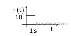
$$g(t)$$ can be expressed as
The laplace transform of $$g(t)$$ is
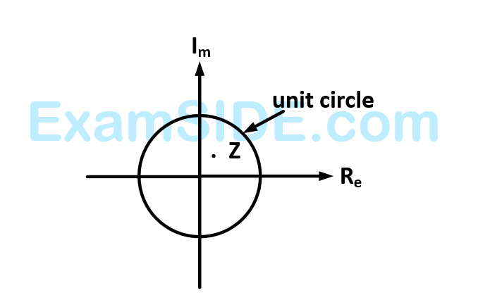
The plot of the complex number $$w = 1/z$$
equation (i) $$10\,{x_2}\,\sin \,{x_1} - 0.8 = 0$$
$$\,\,\,\,\,\,\,\,\,\,\,\,\,\,$$ $$10\,x_2^2\, - 10\,{x_2}\cos \,{x_1} - 0.6 = 0$$
Assuming the initial values $${x_1} = 0.0$$ and $${x_2} = 1.0$$ the Jacobian matrix is

The $$kVA$$ rating of the input transformer is
$${V_i} = 100\sqrt 2 \,\,\,\sin \,\,\,\left( {100\pi t} \right)\,\,V$$
The current drawn by the converter is
$${i_i} = 10\sqrt 2 \,\,\,\sin \,\,\,\left( {100\pi t - {\pi \over 3}} \right)\,\, + 5\sqrt 2 $$
$$\sin \left( {300\pi t + {\pi \over 4}} \right)\,\, + \,\,2\sqrt 2 \,\,\sin \left( {500\pi t - {\pi \over 6}} \right)A$$
The input power factor of the converter is
$${V_i} = 100\sqrt 2 \,\,\,\sin \,\,\,\left( {100\pi t} \right)\,\,V$$
The current drawn by the converter is
$${i_i} = 10\sqrt 2 \,\,\,\sin \,\,\,\left( {100\pi t - {\pi \over 3}} \right)\,\, + 5\sqrt 2 $$
$$\sin \left( {300\pi t + {\pi \over 4}} \right)\,\, + \,\,2\sqrt 2 \,\,\sin \left( {500\pi t - {\pi \over 6}} \right)A$$
The active power drawn by the converter is

The maximum current through the battery will be

The proper configuration for realizing switches $${S_1}$$ to $${S_6}$$ is

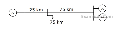

$${G_1} = 250\,\,MVA.\,\,\,15kV,\,\,$$ positive sequence $$X = 25$$% on its own base
$${G_2} = 100\,\,MVA.\,\,\,15kV,\,$$ positive sequence $$X = 10$$% on its own base
$${L_1}$$ and $${L_2}$$ $$= 10$$ $$km,$$ positive sequence $$ X = 0.225$$ $$\,\,\Omega /km$$
In the above system the three-phase fault $$MVA$$ at the bus $$3$$ is
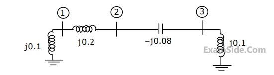
The bus admittance matrix, $$Y$$-$$bus,$$ of the network is
$${G_1} = 250\,\,MVA.\,\,\,15kV,\,\,$$ positive sequence $$X = 25$$% on its own base
$${G_2} = 100\,\,MVA.\,\,\,15kV,\,$$ positive sequence $$X = 10$$% on its own base
$${L_1}$$ and $${L_2}$$ $$= 10$$ $$km,$$ positive sequence $$ X = 0.225$$ $$\,\,\Omega /km$$
For the above system, the positive sequence diagram with the p.u values on the $$100$$ $$MVA$$ common
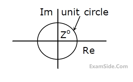 The plot of the complex number $$y=\frac1z$$ is