1
GATE EE 2011
MCQ (Single Correct Answer)
+1
-0.3
A three-phase current source inverter used for the speed control of an induction motor is to be realized using MOSFET switches as shown below. Switches $${S_1}$$ to $${S_6}$$ are identical switches.

The proper configuration for realizing switches $${S_1}$$ to $${S_6}$$ is
A

B

C

D

2
GATE EE 2011
MCQ (Single Correct Answer)
+2
-0.6
A voltage commutated chopper circuit, operated at $$500Hz,$$ is shown below. If the maximum value of load current is $$10A,$$ then the maximum current through the main $$(M)$$ and auxiliary $$(A)$$ thyristors will be

3
GATE EE 2011
MCQ (Single Correct Answer)
+2
-0.6
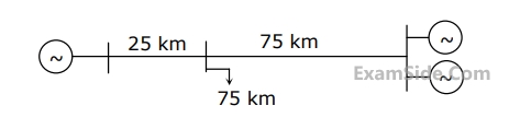
A load center of 120 MW derives power from two power stations connected by 220 kV transmission lines of 25 km and 75 km as shown in the figure below. The three generators G1,G2 and G3 are of 100 MW capacity each and have identical fuel cost characteristics. The minimum loss generation schedule for supplying the 120 MW load is
4
GATE EE 2011
MCQ (Single Correct Answer)
+2
-0.6
Two generator units $$G1$$ and $$G2$$ are connected by $$15$$ $$kV$$ line with a bus at the mid-point as shown below

$${G_1} = 250\,\,MVA.\,\,\,15kV,\,\,$$ positive sequence $$X = 25$$% on its own base
$${G_2} = 100\,\,MVA.\,\,\,15kV,\,$$ positive sequence $$X = 10$$% on its own base
$${L_1}$$ and $${L_2}$$ $$= 10$$ $$km,$$ positive sequence $$ X = 0.225$$ $$\,\,\Omega /km$$
$${G_1} = 250\,\,MVA.\,\,\,15kV,\,\,$$ positive sequence $$X = 25$$% on its own base
$${G_2} = 100\,\,MVA.\,\,\,15kV,\,$$ positive sequence $$X = 10$$% on its own base
$${L_1}$$ and $${L_2}$$ $$= 10$$ $$km,$$ positive sequence $$ X = 0.225$$ $$\,\,\Omega /km$$
In the above system the three-phase fault $$MVA$$ at the bus $$3$$ is
Paper Analysis
Total Questions
Analog Electronics 4
Control Systems 6
Digital Electronics 3
Electric Circuits 5
Electrical and Electronics Measurement 4
Electrical Machines 6
Electromagnetic Fields 1
Engineering Mathematics 10
Power Electronics 7
Power System Analysis 8
Signals and Systems 6
More Papers of GATE EE
GATE EE 2026 GATE EE 2025 GATE EE 2024 GATE EE 2023 GATE EE 2022 GATE EE 2021 GATE EE 2020 GATE EE 2019 GATE EE 2018 GATE EE 2017 Set 2 GATE EE 2017 Set 1 GATE EE 2016 Set 1 GATE EE 2016 Set 2 GATE EE 2015 Set 1 GATE EE 2015 Set 2 GATE EE 2014 Set 3 GATE EE 2014 Set 2 GATE EE 2014 Set 1 GATE EE 2013 GATE EE 2012 GATE EE 2011 GATE EE 2010 GATE EE 2009 GATE EE 2008 GATE EE 2007 GATE EE 2006 GATE EE 2005 GATE EE 2004 GATE EE 2003 GATE EE 2002 GATE EE 2001 GATE EE 2000 GATE EE 1999 GATE EE 1998 GATE EE 1997 GATE EE 1996 GATE EE 1995 GATE EE 1994 GATE EE 1993 GATE EE 1992 GATE EE 1991
GATE EE Papers
All year-wise previous year question papers
2026
2025
2024
2023
2022
2021
2020
2019
2018
2013
2012
2011
2010
2009
2008
2007
2006
2005
2004
2003
2002
2001
2000
1999
1998
1997
1996
1995
1994
1993
1992
1991