1
GATE EE 1999
Subjective
+2
-0
The logic function $$F = AC + ABD + ACD$$ is to be realized using an $$8$$ to $$1$$ multiplexer shown in figure, using $$A, C$$ and $$D$$ as control inputs.
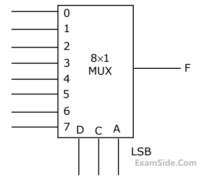
$$(a)$$ Indicate the inputs to be applied at the terminals $$0$$ to $$7.$$
$$(b)$$ Can the function be realize using a $$4$$ to $$1$$ multiplexer?
State YES or NO.
2
GATE EE 1999
MCQ (Single Correct Answer)
+2
-0.6
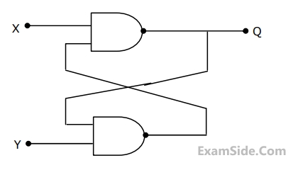
For a flip-flop formed from two $$NAND$$ gates as shown in figure. The unusable state corresponds to
3
GATE EE 1999
MCQ (Single Correct Answer)
+2
-0.6
For a dual $$ADC$$ type $$3\,{\raise0.5ex\hbox{$\scriptstyle 1$}
\kern-0.1em/\kern-0.15em
\lower0.25ex\hbox{$\scriptstyle 2$}}$$ digit $$DVM$$, the reference voltage is $$100$$ $$mV$$ and the first integration time is set to $$300$$ $$ms$$. For some input voltage, the ''deintegration'' period is $$370.2ms.$$ The $$DVM$$ will indicate.
4
GATE EE 1999
Subjective
+5
-0
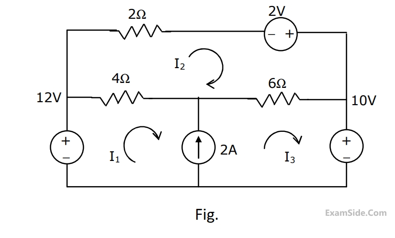
Solve the circuit shown in Fig. using the mesh method of analysis and determine the mesh currents $${{\rm I}_1},\,{{\rm I}_2},$$ and $${{\rm I}_3}$$. Evaluate the power developed in the $$10$$ $$V$$ voltage source.
Paper Analysis
Total Questions
Analog Electronics 6
Control Systems 1
Digital Electronics 4
Electric Circuits 12
Electrical and Electronics Measurement 6
Electrical Machines 13
Electromagnetic Fields 3
Engineering Mathematics 2
Power Electronics 3
Power System Analysis 14
Signals and Systems 1
More Papers of GATE EE
GATE EE 2026 GATE EE 2025 GATE EE 2024 GATE EE 2023 GATE EE 2022 GATE EE 2021 GATE EE 2020 GATE EE 2019 GATE EE 2018 GATE EE 2017 Set 1 GATE EE 2017 Set 2 GATE EE 2016 Set 2 GATE EE 2016 Set 1 GATE EE 2015 Set 1 GATE EE 2015 Set 2 GATE EE 2014 Set 2 GATE EE 2014 Set 3 GATE EE 2014 Set 1 GATE EE 2013 GATE EE 2012 GATE EE 2011 GATE EE 2010 GATE EE 2009 GATE EE 2008 GATE EE 2007 GATE EE 2006 GATE EE 2005 GATE EE 2004 GATE EE 2003 GATE EE 2002 GATE EE 2001 GATE EE 2000 GATE EE 1999 GATE EE 1998 GATE EE 1997 GATE EE 1996 GATE EE 1995 GATE EE 1994 GATE EE 1993 GATE EE 1992 GATE EE 1991
GATE EE Papers
All year-wise previous year question papers
2026
2025
2024
2023
2022
2021
2020
2019
2018
2013
2012
2011
2010
2009
2008
2007
2006
2005
2004
2003
2002
2001
2000
1999
1998
1997
1996
1995
1994
1993
1992
1991