1
GATE EE 2007
MCQ (Single Correct Answer)
+2
-0.6
The associated figure shows the two types of rotate right instruction $${R_1},\,{R_2}$$ available in a microprocessor where Register is a $$8$$-bit register and $$C$$ is the carry bit. The rotate left instructions $$L1$$ and $$L2$$ are similar except that $$C$$ now links the most significant bit of Register instead of the least significant one.

Such a division can be correctly performed by the following set of operations
2
GATE EE 2007
MCQ (Single Correct Answer)
+2
-0.6
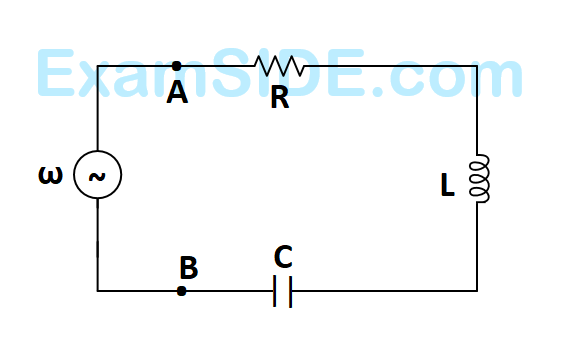
The $$R-L-C$$ series circuit shown is supplied from a variable frequency voltage source. The admittance $$-$$ locus of the $$R-L$$ $$-C$$ network at terminals $$AB$$ for increasing frequency $$\omega $$ is
A

B

C

D

3
GATE EE 2007
MCQ (Single Correct Answer)
+2
-0.6
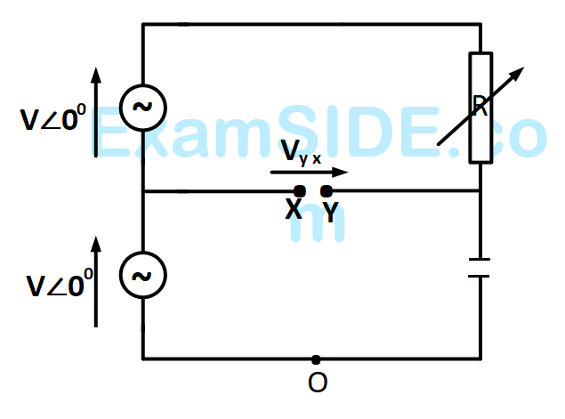
In the figure given below, all phasors are with reference to the potential at point $$''O''.$$ The locus of voltage phasor $${V_{YX}}$$ as $$R$$ is varied from zero to infinity is shown by
A

B

C

D

4
GATE EE 2007
MCQ (Single Correct Answer)
+2
-0.6
In the figure, transformer $${T_1}$$ has two secondaries, all three windings having the same number of turns and with polarities having the same number of turns and with polarities as indicated. One secondary is shorted by a $$10\,\Omega $$ resistor $$R,$$ and the other by a $$15\mu F$$ capacitor. The switch $$SW$$ is opened $$(t=0)$$ when the capacitor is charged to $$5$$ $$V$$ with the left plate as positive. At $$t=0+$$ the voltage $${V_P}$$ and current $${I_R}$$ are

Paper Analysis
Total Questions
Analog Electronics 6
Control Systems 8
Digital Electronics 5
Electric Circuits 8
Electrical and Electronics Measurement 2
Electrical Machines 10
Electromagnetic Fields 4
Engineering Mathematics 8
Power Electronics 11
Power System Analysis 10
Signals and Systems 8
More Papers of GATE EE
GATE EE 2026 GATE EE 2025 GATE EE 2024 GATE EE 2023 GATE EE 2022 GATE EE 2021 GATE EE 2020 GATE EE 2019 GATE EE 2018 GATE EE 2017 Set 2 GATE EE 2017 Set 1 GATE EE 2016 Set 1 GATE EE 2016 Set 2 GATE EE 2015 Set 1 GATE EE 2015 Set 2 GATE EE 2014 Set 3 GATE EE 2014 Set 2 GATE EE 2014 Set 1 GATE EE 2013 GATE EE 2012 GATE EE 2011 GATE EE 2010 GATE EE 2009 GATE EE 2008 GATE EE 2007 GATE EE 2006 GATE EE 2005 GATE EE 2004 GATE EE 2003 GATE EE 2002 GATE EE 2001 GATE EE 2000 GATE EE 1999 GATE EE 1998 GATE EE 1997 GATE EE 1996 GATE EE 1995 GATE EE 1994 GATE EE 1993 GATE EE 1992 GATE EE 1991
GATE EE Papers
All year-wise previous year question papers
2026
2025
2024
2023
2022
2021
2020
2019
2018
2013
2012
2011
2010
2009
2008
2007
2006
2005
2004
2003
2002
2001
2000
1999
1998
1997
1996
1995
1994
1993
1992
1991