1
GATE EE 2017 Set 1
Numerical
+1
-0
In the converter circuit shown below, the switches are controlled such that the load voltage $${v_0}\left( t \right)$$ is a $$400$$ $$Hz$$ square wave.

The RMS value of the fundamental component of $${v_0}\left( t \right)$$ in volts is ___________.
Your input ____
2
GATE EE 2017 Set 1
Numerical
+1
-0
A 10-bus power system consists of four generator buses indexed as G1, G2, G3, G4 and six load buses indexed as L1, L2, L3, L4, L5, L6. The generator bus G1 is considered as slack bus, and the load buses L3 and L4 are voltage controlled buses. The generator at bus G2 cannot supply the required reactive power demand, and hence it is operating at its maximum reactive power limit. The number of non-linear equations required for solving the load flow problem using Newton-Raphson method in polar form is ____________.
Your input ____
3
GATE EE 2017 Set 1
MCQ (Single Correct Answer)
+2
-0.6
The bus admittance matrix for a power system network is
$$$\left[ {\matrix{
{ - j39.9} & {j20} & {j20} \cr
{j20} & { - j39.9} & {j20} \cr
{j20} & {j20} & { - j39.9} \cr
} } \right]\,pu.$$$
There is a transmission line connected between buses $$1$$ and $$3,$$ which is represented by the circuit shown in figure.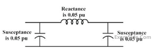
There is a transmission line connected between buses $$1$$ and $$3,$$ which is represented by the circuit shown in figure.
If this transmission line is removed from service what is the modified bus admittance matrix?
4
GATE EE 2017 Set 1
MCQ (Single Correct Answer)
+1
-0.3
A $$3$$-bus power system is shown in the figure below, where the diagonal elements of $$Y$$-bus matrix are: $${Y_{11}} = - j12\,pu,\,\,\,{Y_{22}} = - j15\,pu\,\,$$ and $$\,{Y_{33}} = - j7\,pu.$$
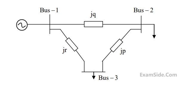
The per unit values of the line reactance's $$p, q$$ and $$r$$ shown in the figure are
Paper Analysis
Total Questions
Analog Electronics 3
Control Systems 7
Digital Electronics 3
Electric Circuits 4
Electrical and Electronics Measurement 3
Electrical Machines 7
Electromagnetic Fields 3
Engineering Mathematics 6
Power Electronics 5
Power System Analysis 7
Signals and Systems 4
More Papers of GATE EE
GATE EE 2026 GATE EE 2025 GATE EE 2024 GATE EE 2023 GATE EE 2022 GATE EE 2021 GATE EE 2020 GATE EE 2019 GATE EE 2018 GATE EE 2017 Set 2 GATE EE 2017 Set 1 GATE EE 2016 Set 1 GATE EE 2016 Set 2 GATE EE 2015 Set 1 GATE EE 2015 Set 2 GATE EE 2014 Set 3 GATE EE 2014 Set 2 GATE EE 2014 Set 1 GATE EE 2013 GATE EE 2012 GATE EE 2011 GATE EE 2010 GATE EE 2009 GATE EE 2008 GATE EE 2007 GATE EE 2006 GATE EE 2005 GATE EE 2004 GATE EE 2003 GATE EE 2002 GATE EE 2001 GATE EE 2000 GATE EE 1999 GATE EE 1998 GATE EE 1997 GATE EE 1996 GATE EE 1995 GATE EE 1994 GATE EE 1993 GATE EE 1992 GATE EE 1991
GATE EE Papers
All year-wise previous year question papers
2026
2025
2024
2023
2022
2021
2020
2019
2018
2013
2012
2011
2010
2009
2008
2007
2006
2005
2004
2003
2002
2001
2000
1999
1998
1997
1996
1995
1994
1993
1992
1991