1
GATE EE 2017 Set 1
Numerical
+2
-0
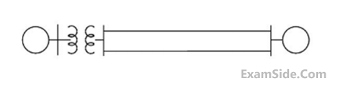
The figure shows the single line diagram of a power system with a double circuit transmission line. The expression for electrical power is $$\,1.5\,\,\sin \delta ,\,\,$$ where $$\delta $$ is the rotor angle. The system is operating at the stable equilibrium point with mechanical power equal to $$1$$ pu. If one of the transmission line circuits is removed, the maximum value of $$\delta ,$$ as the rotor swings is $$1.221$$ radian. If the expression for electrical power with one transmission line circuit removed is $$\,{P_{\max }}\,\sin \delta ,\,\,$$ the valueof $${P_{\max }}\,,$$ in pu is _________.
Your input ____
2
GATE EE 2017 Set 1
Numerical
+2
-0
The positive, negative and zero sequence reactances of a wye-connected synchronous generator are 0.2 pu, 0.2 pu, and 0.1 pu, respectively. The generator is on open circuit with a terminal voltage of 1 pu. The minimum value of the inductive reactance, in pu, required to be connected between neutral and ground so that the fault current does not exceed 3.75 pu if a single line to ground fault occurs at the terminals is _______ (assume fault impedance to be zero). (Give the answer up to one decimal place)
Your input ____
3
GATE EE 2017 Set 1
MCQ (Single Correct Answer)
+2
-0.6
Let the signal $$$x\left(t\right)=\sum_{k=-\infty}^{+\infty}\left(-1\right)^k\delta\left(t-\frac k{2000}\right)$$$ be passed through an LTI system with frequency
response $$H\left(\omega\right)$$, as given in the figure below
 The Fourier series representation of the output is given as
The Fourier series representation of the output is given as4
GATE EE 2017 Set 1
Numerical
+1
-0
Consider $$$g\left(t\right)=\left\{\begin{array}{l}t-\left\lfloor t\right\rfloor,\\t-\left\lceil t\right\rceil,\end{array}\right.\left.\begin{array}{r}t\geq0\\otherwise\end{array}\right\}$$$ where $$t\;\in\;R$$
Here, $$\left\lfloor t\right\rfloor$$ represents the largest integer less than or equal to t and $$\left\lceil t\right\rceil$$ denotes the smallest integer greater than or equal to t. The coefficient of the second harmonic component of the Fourier series representing g(t) is _________.
Here, $$\left\lfloor t\right\rfloor$$ represents the largest integer less than or equal to t and $$\left\lceil t\right\rceil$$ denotes the smallest integer greater than or equal to t. The coefficient of the second harmonic component of the Fourier series representing g(t) is _________.
Your input ____
Paper Analysis
Total Questions
Analog Electronics 3
Control Systems 7
Digital Electronics 3
Electric Circuits 4
Electrical and Electronics Measurement 3
Electrical Machines 7
Electromagnetic Fields 3
Engineering Mathematics 6
Power Electronics 5
Power System Analysis 7
Signals and Systems 4
More Papers of GATE EE
GATE EE 2026 GATE EE 2025 GATE EE 2024 GATE EE 2023 GATE EE 2022 GATE EE 2021 GATE EE 2020 GATE EE 2019 GATE EE 2018 GATE EE 2017 Set 2 GATE EE 2017 Set 1 GATE EE 2016 Set 1 GATE EE 2016 Set 2 GATE EE 2015 Set 1 GATE EE 2015 Set 2 GATE EE 2014 Set 3 GATE EE 2014 Set 2 GATE EE 2014 Set 1 GATE EE 2013 GATE EE 2012 GATE EE 2011 GATE EE 2010 GATE EE 2009 GATE EE 2008 GATE EE 2007 GATE EE 2006 GATE EE 2005 GATE EE 2004 GATE EE 2003 GATE EE 2002 GATE EE 2001 GATE EE 2000 GATE EE 1999 GATE EE 1998 GATE EE 1997 GATE EE 1996 GATE EE 1995 GATE EE 1994 GATE EE 1993 GATE EE 1992 GATE EE 1991
GATE EE Papers
All year-wise previous year question papers
2026
2025
2024
2023
2022
2021
2020
2019
2018
2013
2012
2011
2010
2009
2008
2007
2006
2005
2004
2003
2002
2001
2000
1999
1998
1997
1996
1995
1994
1993
1992
1991