Sinusoidal Steady State Response · Network Theory · GATE ECE
Marks 1
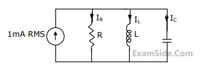
Let $i_C, i_L$, and $i_R$ be the currents flowing through the capacitor, inductor, and resistor, respectively, in the circuit given below. The AC admittances are given in Siemens(S). Which one of the following is true?

A series $$RLC$$ circuit has a quality factor Q of 1000 at a center frequency of $$10^6$$ rad/s. The possible values of R, L and C are
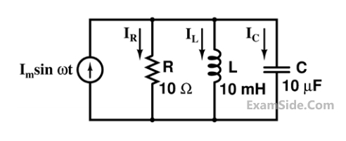
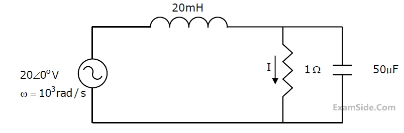
At response, the ratio $$\left| {{{\rm I}_L}} \right|/\left| {{{\rm I}_R}} \right|$$, i.e., the ratio of the magnitudes of the inductor current phasor and the resistor current phasor, is _________.
$$i(t)$$$$ = 3 + 4\sin \left( {100t + {{45}^ \circ }} \right) + 4\sin \left( {300t + {{60}^ \circ }} \right)\,\,A$$.
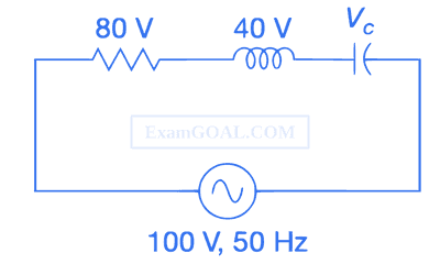
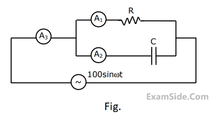
The RMS value of the current and the power dissipated in the circuit are
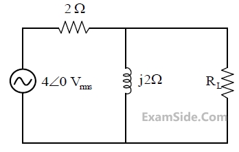
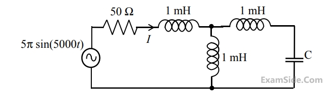
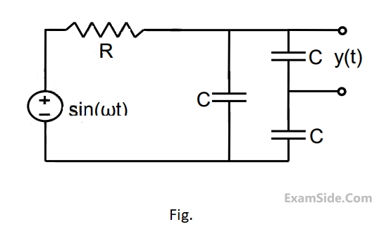
Marks 2
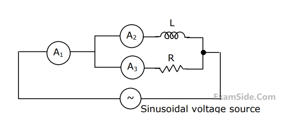
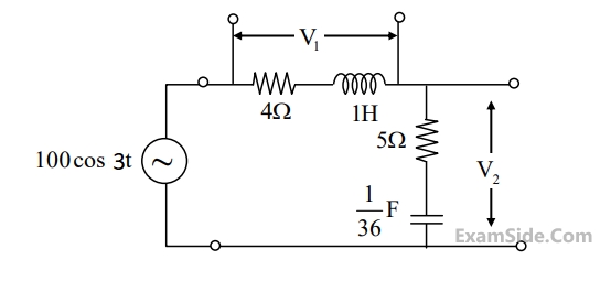
In the circuit below, $M_1$ is an ideal AC voltmeter and $M_2$ is an ideal AC ammeter. The source voltage (in Volts) is $v_s(t)=100 \cos (200 t)$.
What should be the value of the variable capacitor $C$ such that the RMS readings on $M_1$ and $M_2$ are 25 V and 5 A , respectively?

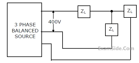
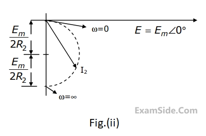
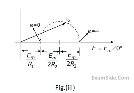
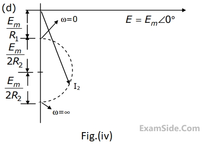
For the circuit shown, the locus of the impedance Z(j$$\omega$$) is plotted as $$\omega$$ increases from zero to infinity. The values of R1 and R2 are :

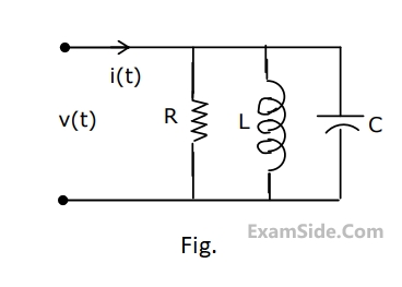
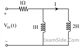
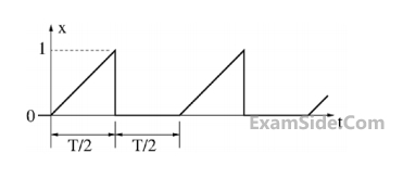
Consider the circuit shown in the figure with input V(t) in volts. The sinusoidal steady state current I(t) flowing through the circuit is shown graphically (where t is in seconds). The circuit element Z can be _________.


where $$'t'$$ is in seconds. The time (in seconds) at which the current $${\rm I}$$ in the circuit will reach the value $$2$$ Ampere is ______ .
$$\sum\limits_{k = 1}^3 {{a_k}\,\,\cos \,\left( {k{\omega _0}t} \right),\,\,\,} $$ where $${a_k} \ne 0,\,\,{\omega _0} \ne 0$$.
The source has nonzero impedance. Which one of the following is a possible form of the output measured across a resistor in the network?
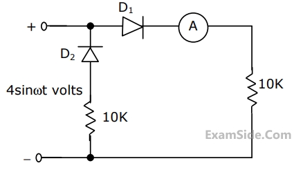
An AC voltage source V = 10 sin(t) volts is applied to the following network. Assume that R1 = 3 kΩ, R2 = 6 kΩ and R3 = 9 kΩ and that the diode is ideal.
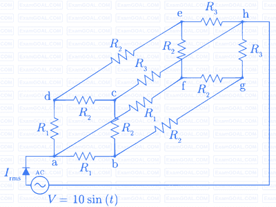
RMS current Irms (in mA) through the diode is _________.
If the amplitude $$\left| {{\rm A}\left( \omega \right)} \right| = 0.25$$, then the frequency $$\omega $$ is
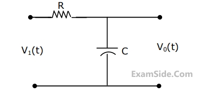
Let $$C = 100\,\mu F\,\,$$ and $$R = 10\,k\Omega $$.
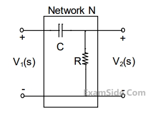
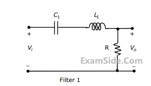
Two such blocks are connected in cascade, as shown in the figure.
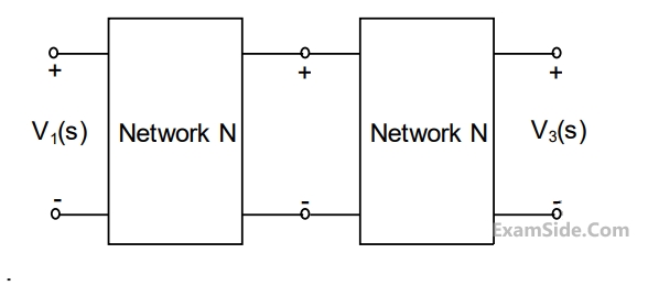
The transfer function $${{{V_3}\left( s \right)} \over {{V_1}\left( s \right)}}$$ of the cascaded network is

Consider the following statements S1 and S2.
S1: The $$\beta$$ of a bipolar transistor reduces if the base width is increased.
S2: The $$\beta$$ of a bipolar transistor increases if the doping concentration in the base in increased
Which one of the following is correct?$$H\left( s \right) = {{{{10}^6}} \over {{s^2} + 20s + {{10}^6}}}$$
The Quality factor (Q-factore) of this circuit is
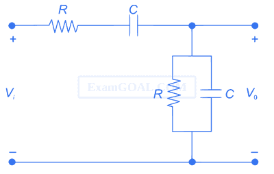
The condition for the RC network to act as a phase lead controller is

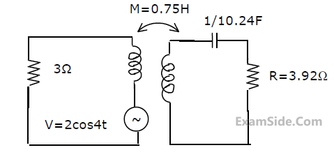
Marks 5
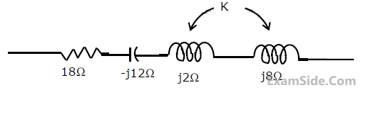
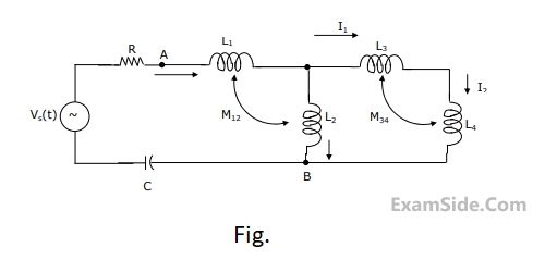
$${L_1} = 2\,H,\,{L_2} = 5\,H,\,{L_3}\, = \,1H,{L_4} = 4H\,\,\,$$ and $$C - 0.2\,\,\mu F.$$. The mutual inductances are $${M_{12}} = 3\,H$$ and $${M_{34}} = 2\,H$$.
Determine
(a) the equivalent inductance for the combination of $${L_3}$$ and $${L_4}$$,
(b) the equivalent inductance across the points A and B in the network,
(c) the resonant frequency of the network.
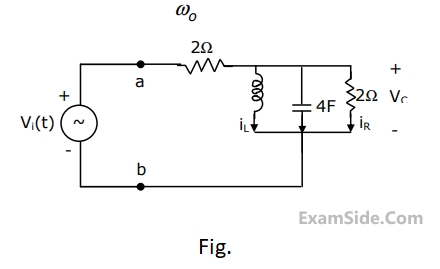
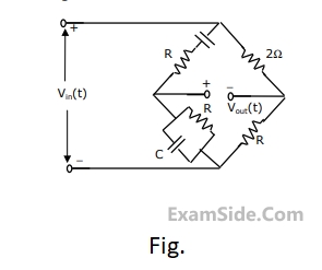
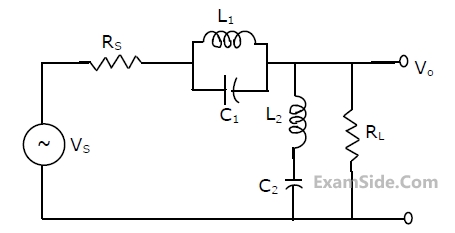
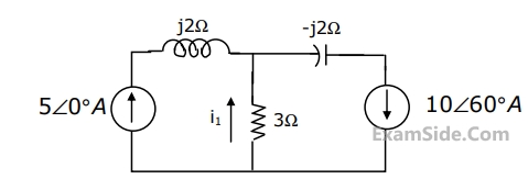
(a)Find the frequency $${\omega _0}$$ at which the magnitude of the impedance across terminals a, b reaches maximum.
(b) Find the impedance across a, b at the frequency $${\omega _0}$$.
(c) If $${v_i}\left( t \right) = V\,\,\sin \left( {{\omega _0}t} \right),$$ find $${i_L}\left( t \right),\,\,{i_c}\left( t \right),{i_R}\left( t \right).$$

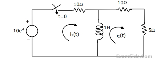
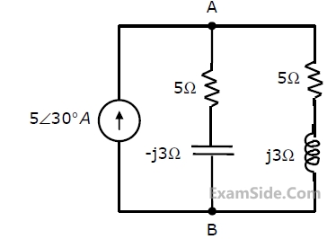
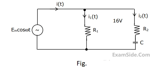
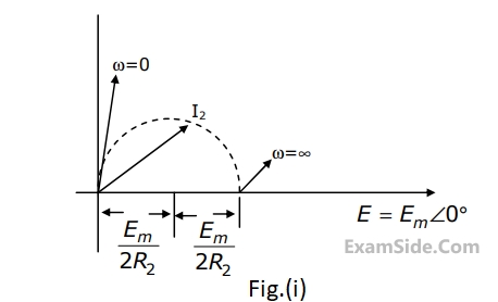
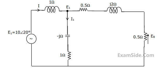
(a) Find the impedance to the right of $$\left( {A,\,\,\,\,\,\,B} \right)$$ at $$\omega \,\,\, = \,\,\,\,0$$ rad/sec and $$\omega \,\,\, = \,\,\,\,\infty $$ rad/sec.
(b) If $$\omega \,\,\, = \,\,\,\,{\omega _0}$$ rad/sec and $${i_1}\left( t \right) = \,\,{\rm I}\,\,\,\sin \,\left( {{\omega _0}t} \right)\,{\rm A},$$ where $${\rm I}$$ is positive, $${{\omega _0}\,\, \ne \,\,0}$$, $${{\omega _0}\,\, \ne \,\,\infty }$$, then find $${\rm I}$$, $${{\omega _0}}$$ and $${i_2}\left( t \right)$$