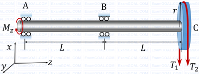
A shaft AC rotating at a constant speed carries a thin pulley of radius r = 0.4 m at the end C which drives a belt. A motor is coupled at the end A of the shaft such that it applies a torque M, about the shaft axis without causing any bending moment. The shaft is mounted on narrow frictionless bearings at A and B where AB = BC = L = 0.5 m. The taut and slack side tensions of the belt are T1 = 300 N and T2 = 100 N, respectively. The allowable shear stress for the shaft material is 80 MPa. The self-weights of the pulley and the shaft are negligible. Use the value of π available in the on-screen virtual calculator. Neglecting shock and fatigue loading and assuming maximum shear stress theory, the minimum required shaft diameter is mm (round off to 2 decimal places).

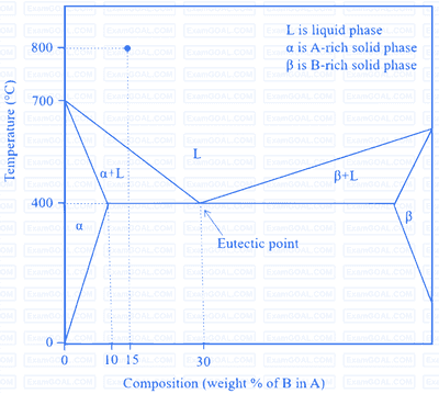
Fluidity of a molten alloy during sand casting depends on its solidification range. The phase diagram of a hypothetical binary alloy of components A and B is shown in the figure with its eutectic composition and temperature. All the lines in this phase diagram, including the solidus and liquidus lines, are straight lines. If this binary alloy with 15 weight % of B is poured into a mould at a pouring temperature of 800 °C, then the solidification range is

A shaft of diameter $25^{-0.04}_{-0.07}$ mm is assembled in a hole of diameter $25^{+0.02}_{-0.00}$ mm. Match the allowance and limit parameter in Column I with its corresponding quantitative value in Column II for this shaft-hole assembly.
|
Allowance and limit parameter (Column I) |
Quantitative value (Column II) |
||
|
P. |
Allowance |
1. |
0.09 mm |
|
Q. |
Maximum clearance |
2. |
24.96 mm |
|
R. |
Maximum material limit for hole |
3. |
0.04 mm |
|
|
|
4. |
25.0 mm |