1
GATE EE 2014 Set 1
Numerical
+2
-0
In the figure, the value of resistor R is $$\left(25+\frac{\mathrm I}2\right)\mathrm\Omega$$, where I is the current in amperes.
The current I is _____.

Your input ____
2
GATE EE 2014 Set 1
Numerical
+1
-0
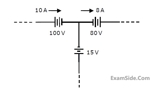
The three circuit elements shown in the figure are part of an electric circuit. The total power
absorbed by the three circuit elements in watts is ________________.
Your input ____
3
GATE EE 2014 Set 1
MCQ (Single Correct Answer)
+1
-0.3
C0 is the capacitance of a parallel plate capacitor with air as dielectric (as in figure (a)). If,
half of the entire gap as shown in figure (b) is filled with a dielectric of permittivity $$\in_r$$ , the
expression for the modified capacitance is

4
GATE EE 2014 Set 1
MCQ (Single Correct Answer)
+1
-0.3
A combination of 1μF capacitor with an initial voltage Vc(0) = −2V in series with a 100Ω
resistor is connected to a 20 mA ideal dc current source by operating both switches at t = 0s
as shown. Which of the following graphs shown in the options approximates the voltage Vs
across the current source over the next few seconds?

A

B

C

D

Paper Analysis
Total Questions
Analog Electronics 5
Control Systems 4
Digital Electronics 3
Electric Circuits 5
Electrical and Electronics Measurement 4
Electrical Machines 7
Electromagnetic Fields 1
Engineering Mathematics 8
Power Electronics 4
Power System Analysis 8
Signals and Systems 5
More Papers of GATE EE
GATE EE 2026 GATE EE 2025 GATE EE 2024 GATE EE 2023 GATE EE 2022 GATE EE 2021 GATE EE 2020 GATE EE 2019 GATE EE 2018 GATE EE 2017 Set 1 GATE EE 2017 Set 2 GATE EE 2016 Set 2 GATE EE 2016 Set 1 GATE EE 2015 Set 1 GATE EE 2015 Set 2 GATE EE 2014 Set 2 GATE EE 2014 Set 3 GATE EE 2014 Set 1 GATE EE 2013 GATE EE 2012 GATE EE 2011 GATE EE 2010 GATE EE 2009 GATE EE 2008 GATE EE 2007 GATE EE 2006 GATE EE 2005 GATE EE 2004 GATE EE 2003 GATE EE 2002 GATE EE 2001 GATE EE 2000 GATE EE 1999 GATE EE 1998 GATE EE 1997 GATE EE 1996 GATE EE 1995 GATE EE 1994 GATE EE 1993 GATE EE 1992 GATE EE 1991
GATE EE Papers
All year-wise previous year question papers
2026
2025
2024
2023
2022
2021
2020
2019
2018
2013
2012
2011
2010
2009
2008
2007
2006
2005
2004
2003
2002
2001
2000
1999
1998
1997
1996
1995
1994
1993
1992
1991