Sequential Circuits · Digital Logic · GATE CSE
Marks 1
In a 4-bit ripple counter, if the period of the waveform at the last flip-flop is 64 microseconds, then the frequency of the ripple counter in kHz is _________. (Answer in integer)
The output of a 2-input multiplexer is connected back to one of its inputs as shown in the figure.

Match the functional equivalence of this circuit to one of the following options.

The number of states in the state transition diagram of this circuit that have a transition back to the same state on some value of “in” is _____.
Marks 2
Consider a 2-bit saturating up/down counter that performs the saturating up count when the input $P$ is 0 , and the saturating down count when $P$ is 1 . The Next State table of the counter is as shown. The counter is built as a synchronous sequential circuit using $D$ flip-flops.
| Inpur | Current state | Next state | ||
|---|---|---|---|---|
| $$ P $$ |
$$ Q_1 $$ |
$$ Q_0 $$ |
$$ Q_1^{+} $$ |
$$ Q_0^{+} $$ |
| $$ \begin{aligned} & 0 \\ & 0 \\ & 0 \\ & 0 \\ & 1 \\ & 1 \\ & 1 \\ & 1 \end{aligned} $$ |
$$ \begin{aligned} & 0 \\ & 0 \\ & 1 \\ & 1 \\ & 0 \\ & 0 \\ & 1 \\ & 1 \end{aligned} $$ |
$$ \begin{aligned} & 0 \\ & 1 \\ & 0 \\ & 1 \\ & 0 \\ & 1 \\ & 0 \\ & 1 \end{aligned} $$ |
$$ \begin{aligned} & 0 \\ & 1 \\ & 1 \\ & 1 \\ & 0 \\ & 0 \\ & 0 \\ & 1 \end{aligned} $$ |
$$ \begin{aligned} & 1 \\ & 0 \\ & 1 \\ & 1 \\ & 0 \\ & 0 \\ & 1 \\ & 0 \end{aligned} $$ |
Consider the given sequential circuit designed using D-Flip-flops. The circuit is initialized with some value (initial state). The number of distinct states the circuit will go through before returning back to the initial state is _________ . (Answer in integer)

Consider a sequential digital circuit consisting of T flip-flops and D flip-flops as shown in the figure. CLKIN is the clock input to the circuit. At the beginning, Q1, Q2 and Q3 have values 0, 1 and 1, respectively.

Which one of the given values of (Q1, Q2, Q3) can NEVER be obtained with this digital circuit?
Consider a digital display system (DDS) shown in the figure that displays the contents of register X. A 16-bit code word is used to load a word in X, either from S or from R. S is a 1024-word memory segment and R is a 32-word register file. Based on the value of mode bit M, T selects an input word to load in X. P and Q interface with the corresponding bits in the code word to choose the addressed word. Which one of the following represents the functionality of P, Q, and T?

Suppose we want to design a synchronous circuit that processes a string of 0’s and 1’s. Given a string, it produces another string by replacing the first 1 in any subsequence of consecutive 1’s by a 0. Consider the following example.
Input sequence : 00100011000011100
Output sequence : 00000001000001100
A Mealy Machine is a state machine where both the next state and the output are functions of the present state and the current input.
The above mentioned circuit can be designed as a two-state Mealy machine. The states in the Mealy machine can be represented using Boolean values 0 and 1. We denote the current state, the next state, the next incoming bit, and the output bit of the Mealy machine by the variables s, t, b and y respectively.
Assume the initial state of the Mealy machine is 0.
What are the Boolean expressions corresponding to t and y in terms of s and b ?
Consider a 3-bit counter, designed using T flip-flop, as shown below:

Assuming the initial state of the counter given by PQR as 000, what are the next three states?

The above synchronous sequential circuit built using $$JK$$ flip-flops is initialized with $${Q_2}{Q_1}{Q_0} = 000.\,\,$$ The state sequence for this circuit for the next $$3$$ clock cycles is

If at some instance prior to the occurrence of the clock edge, $$P, Q$$ and $$R$$ have a value $$0,1$$ and $$0$$ respectively, what shall be the value of $$PQR$$ after the clock edge?
If all the flip-flops were reset to $$0$$ at power on, what is the total number of distinct outputs (states) represented by $$PQR$$ generated by the counter?
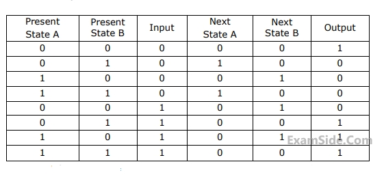
If the initial state is $$A = 0, B=0.$$ What is the minimum length of an input string which will take the machine to the state $$A=0, B=1$$ with Output$$=1?$$
The counter is connected as follows:
Assume that the counter and gate delays are negligible. If the counter starts at $$0,$$ then it cycles through the following sequence:
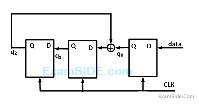
The following data: $$100110000$$ is supplied to the ''data'' terminal in nine clock cycles. After that the values of $${q_2}{q_1}{q_0}$$ are

To complete the circuit, the input $$X$$ should be
Let $${z_k},\,{n_k}$$ denote the number of $$0’s$$ and $$1’s$$ respectively in initial $$k$$ bits of the input
$$\left({{z_k} + {n_k} = k} \right).$$ The circuit outputs $$00$$ until one of the following conditions holds.
$$ * \,\,\,\,\,$$ $${z_k} = {n_k} + 2.\,\,\,$$ In this case, the output at the $$k$$-th and all subsequent clock ticks is $$10.$$
$$ * \,\,\,\,\,$$ $${n_k} = {z_k} + 2.\,\,\,$$ In this case, the output at the $$k$$-th and all subsequent clock ticks is $$01.$$
What is the minimum number of states required in the state transition graph of the above circuit?

Consider the following timing diagram of $$X$$ and $$C;$$ the clock period of $$C>40$$ nanosecond which one is the correct plot of $$Y?$$


Which one of the following is correct state sequence of the circuit?

Has the initial state of $$P, Q$$ as $$0, 1$$ (respectively). After three clock cycles the output states $$P, Q$$ is (respectively).

Marks 5

(a) Draw a state diagram which is implemented by the circuit. Use the following names for the states corresponding to the values of flip-flops as given below.

(b) Given that the initial state of the circuit is $${S_4},$$ identify the set of states which are not reachable.

What is the modules of the counter with initial state $${Q_2}\,{Q_1}\,{Q_0} = 000$$