Capacitor · Physics · MHT CET
MCQ (Single Correct Answer)
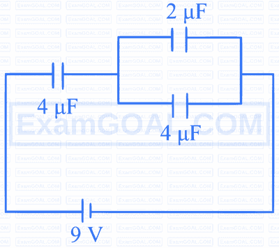
The potential difference across the 4 capacitor in the following circuit is
A capacitor of unknown capacity is connected across a battery of V volt. The charge stored in it is Q coulomb. When potential across the capacitor is reduced by $\mathrm{V}_1$ volt, the charge stored in it becomes $\mathrm{Q}_1$ coulomb. The potential V is
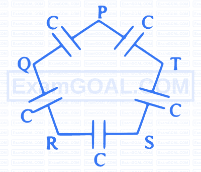
Five capacitors, each of capacitance ' $C$ ' are connected as shown in the figure. The ratio of equivalent capacitance between P and R and the equivalent capacitance between P and Q is
The function of a dielectric in a capacitor is
Three capacitors are connected to a battery as shown in figure. The ratio of charge on capacitors $\mathrm{C}_3$ and $\mathrm{C}_1$ is

The capacity of air filled parallel plate capacitor is $\mathrm{C}_0$. One-half of the space between the plates is filled with a dielectric constant ' K ' as shown in figure. The new capacity becomes $\mathrm{C}_{\mathrm{n}}$. The ratio $\mathrm{C}_{\mathrm{n}}$ to $\mathrm{C}_0$ is

Seven capacitors each of capacitance $2 \mu \mathrm{~F}$ are to be connected in a configuration to obtain an effective capacitance $\left(\frac{10}{11}\right) \mu \mathrm{F}$. The combination is
Two identical metal plates are given charges $q_1$ and $q_2\left(q_2 < q_1\right)$ respectively. If they are now brought close together to form a parallel plate capacitor with capacitance ' C ', the potential difference ' $V$ ' between the plates is
Five capacitors, each of capacity ' $C$ ' are connected as shown in the figure. The resultant capacity between A and B is $14 \mu \mathrm{~F}$. The capacity of each capacitor is
Two capacitors of $100 \mu \mathrm{~F}$ and $50 \mu \mathrm{~F}$ are connected in parallel. If the potential difference across $100 \mu \mathrm{~F}$ is 20 V and across $50 \mu \mathrm{~F}$ is 40 V , then the common potential of the parallel combination will be (same polarities of the capacitor connected together)
A $4 \mu \mathrm{~F}$ capacitor is charged to 10 V . The battery is then disconnected and a pure 10 mH coil is connected across the capacitor so that LC oscillations are set up. The maximum current in the coil is
A parallel plate air capacitor has capacity ' $C$ ' and distance of separation between plates is ' $d$ '. If a conducting sheet of thickness $\frac{2 d}{3}$ is inserted in between the plates, the capacitance becomes $C_1$. The ratio of $\frac{C_1}{C}$ is
Initially $n$ identical capacitors are joined in parallel and are charged to potential V. Now they are separated and joined in series. Then
A series combination of 10 capacitors, each of value ' $\mathrm{C}_1$ ' is charged by a source of potential difference ' 4 V '. When another parallel combination of 8 capacitors, each of value ' $\mathrm{C}_2$ ' is charged by a source of potential difference ' V ', it has the same total energy stored in it as in the first combination. The value of ' $\mathrm{C}_2$ ' is
The graph shows the variation of voltage (v) across the plates of two parallel plate capacitos $A$ and $B$ versus increase of charge $Q$ stored in them. Then

Three capacitors each of capacitance ' C ' and breakdown voltage ' $V$ ' are connected in series. The capacitance and breakdown voltage of the series combination will be respectively
If the charge on the capacitor is increased by 3C, the energy stored in it increases by $21 \%$. The original charge on the capacitor is
A parallel plate capacitor having plate area ' $A$ ' and separation ' $d$ ' is charged to a potential difference ' $V$ '. The charging battery is disconnected and the plates are pulled apart to four times the initial separation. The work required to increase the distance between the plates is ( $\varepsilon_0=$ permittivity of free space)
A parallel plate capacitor has plate area $50 \mathrm{~cm}^2$ and plate separation 3 mm . The space between the plates is filled with a dielectric medium of thickness 1 mm and dielectric constant 4 . The capacitance becomes ( $\varepsilon_0=$ permittivity of free space)
The equivalent capacitance between plates ' A ' and ' B ' ( A -area of each plate, d-separation between plates) ( $\varepsilon_0$ - permittivity of free space) is
The voltage between the plates of a parallel plate capacitor of capacity $1 \mu \mathrm{~F}$ is changing at the rate of $4 \mathrm{~V} / \mathrm{s}$. the displacement current in the capacitor is
A parallel plate air capacitor has capacitance $C_P$. It is equally filled with parallel layers of materials of dielectric constants $\mathrm{K}_1$ and $\mathrm{K}_2$. Now its capacity becomes $C_K$. The ratio $C_P$ to $C_K$ is
A parallel plate capacitor with plate area A and plate separation $d$ is charged by constant current $I$. A plane surface of area $\frac{\mathrm{A}}{2}$, parallel to the plates is drawn simultaneously between the plates. The displacement current through this area is
Two parallel plate air c apacitors of same capacity ' C ' are connected in parallel to a battery of e.m.f. ' $E$ '. Then one of the capacitors is completely filled with dielectric mnaterial of constant ' K '. The change in the effective capacity of the parallel combination is
The graph shows the variation of voltage ' V ' across the plates of two capacitors $A$ and $B$ versus increase in charge ' $Q$ ' stored in them. Then

Air capacitor has capacitance ' $\mathrm{C}_1$ '. The space between two plates of capacitor is filled with two dielectrics as shown in figure. The new capacitance of the capacitor is ' $\mathrm{C}_2$ '. The ratio $\frac{C_1}{C_2}$ is $(d=$ distance between two plates of capacitor, $\mathrm{K}_1$ and $\mathrm{K}_2$ are dielectric constants of two dielectrics respectively)

Two identical capacitors A and B are connected in series to a battery of E.M.F., 'E'. Capacitor B contains a slab of dielectric constant $\mathrm{K} . \mathrm{Q}_{\mathrm{A}}$ and $\mathrm{Q}_{\mathrm{B}}$ are the charges stored in A and B . When the dielectric slab is removed, the corresponding charges are $\mathrm{Q}_{\mathrm{A}}^{\prime}$ and $\mathrm{Q}_{\mathrm{B}}^{\prime}$. Then
A series combination of $n_1$ capacitors, each of value $C_1$ is charged by a source of potential difference 6 V . Another parallel combination of $\mathrm{n}_2$ capacitors, each of value $\mathrm{C}_2$ is charged by a source of potential difference 2 V . Total energy of both the combinations is same. The value of $\mathrm{C}_2$ in terms of $\mathrm{C}_1$ is
In the circuit shown in the following figure, the potential difference cross $3 \mu \mathrm{~F}$ capacitor is

Three condensers of capacities ' $\mathrm{C}_1$ ', ' $\mathrm{C}_2$ ', ' $\mathrm{C}_3$ ' are connected in series with a source of e.m.f. ' $V$ '. The potentials across the three condensers are in the ratio
When three capacitors of equal capacities are connected in parallel and one of the same capacity, capacitor is connected in series with the combination. The resultant capacity is $4.5 \mu \mathrm{~F}$. The capacity of each capacitor is
Two parallel plate air capacitors of same capacity ' C ' are connected in series to a battery of emf ' $E$ '. Then one of the capacitors is completely filled with dielectric material of constant ' K '. The change in the effective capacity of the series combination is
Seven capacitors each of capacitance $2 \mu \mathrm{~F}$ are connected in a configuration to obtain an effective capacitance $\frac{6}{13} \mu \mathrm{~F}$. The combination which will achieve this will have
Two identical capacitors have the same capacitance ' $C$ '. One of them is charged to potential $\mathrm{V}_1$ and other to $\mathrm{V}_2$. The negative ends of capacitors are connected together. When positive ends are also connected, the decrease in energy of the combined system is
The potential difference that must be applied across the series and parallel combination of 4 identical capacitors is such that the energy stored in them becomes the same. The ratio of potential difference in series to parallel combination is
Air capacitor has capacitance of $1 \mu \mathrm{~F}$. Now the space between two plates of capacitor is filled with two dielectrics as shown in figure. The capacitance of the capacitor is [ $\mathrm{d}=$ distance between two plates of capacitor, $\mathrm{K}_1$ and $\mathrm{K}_2$ are dielectric constants of first dielectric and second dielectric respectively]

The function of dielectric in a capacitor is
In the given circuit diagram, in the steady state the current through the battery and the charge on the capacitor respectively are

A parallel plate capacitor of capacitance ' $C$ ' is connected to a battery and charged to a potential difference ' $V$ '. Another capacitor of capacitance 3 C is similarly charged to a potential difference 3 V . The charging battery is then disconnected and capacitors are connected in parallel to each other in such a way that positive terminal of one is connected to the negative terminal of the other. The final energy of the configuration is
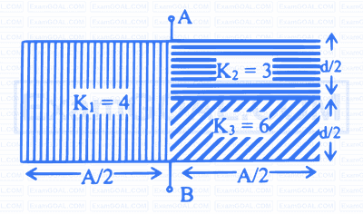
A parallel plate air capacitor, with plate separation ' d ' has a capacitance of 9 pF . The space between the plates is now filled with two dielectrics, the first having $\mathrm{K}_1=3$ and thickness $\mathrm{d}_1=\mathrm{d} / 3$, while the $2^{\text {nd }}$ has $\mathrm{K}_2=6$ and thickness $d_2=2 \mathrm{~d} / 3$. The capacitance of the new capacitor is :
A parallel plate capacitor has plate area $40 \mathrm{~cm}^2$ and plate separation 2 mm . The space between the plates is filled with a dielectric medium of thickness 1 mm and dielectric constant 5 . The capacitance of the system is ( $\varepsilon_0=$ permittivity of vacuum)
A parallel plate capacitor is charged and then isolated. If the separation between the plates is increased, which one of the following statement is NOT correct?
Two circular metal plates each of radius ' $r$ ' are kept parallel to each other distance ' $d$ ' apart. The capacitance of the capacitor formed is ' $\mathrm{C}_1$ '. If the radius of each of the plates is increased to $\sqrt{2}$ times the earlier radius and their distance of separation decreased to half the initial value, the capacitance now becomes ' $\mathrm{C}_2$ '. The ratio of the capacitances $\mathrm{C}_1: \mathrm{C}_2$ is
The amount of work done in increasing the voltage across the plates of a capacitor form 5 V to 10 V is ' W '. The work done in increasing it from 10 V to 15 V will be (nearly)
Charge on a parallel plate capacitor of capacity C is Q , the electric field intensity between its two plates separated by a distance of $t$ is
A circuit having a self inductance of 1 henry carries a current of 1 A . To prevent the sparking when the circuit is broken, a capacitor which can withstand 500 V is connected across the switch. What is the minimum value of the capacitance of the capacitor?
A parallel plate capacitor with air medium between the plates has a capacitance of $$10 \mu \mathrm{F}$$. The area of capacitor is divided into two equal halves and filled with two media (as shown in figure) having dielectric constant $$K_1=2$$ and $$\mathrm{K}_2=4$$. The capacitance of the system will be

Two condensers one of capacity $$\frac{\mathrm{C}}{2}$$ and other capacity $$\mathrm{C}$$ are connected to a battery of voltage $$\mathrm{V}$$ as shown. The work done in charging fully both the condensers is

Which of the following combination of 7 identical capacitors each of $$2 \mu \mathrm{F}$$ gives a capacitance of $$\frac{10}{11} \mu \mathrm{F}$$ ?
In a parallel plate capacitor with air between the plates, the distance $$d$$ between the plates is changed and the space is filled with dielectric constant 8. The capacity of the capacitor is increased 16 times, the distance between the plates is
In the given figure, the equivalent capacitance between points A and B is

If the charge on the capacitor is increased by 3 coulombs, the energy stored in it increases by $$44 \%$$. The original charge on the capacitor is
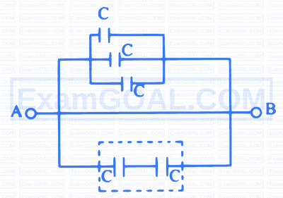
In the given capacitive network the resultant capacitance between point $$\mathrm{A}$$ and $$\mathrm{B}$$ is

The equivalent capacity between terminal $$\mathrm{A}$$ and $$\mathrm{B}$$ is

The potential on the plates of capacitor are $$+20 \mathrm{~V}$$ and $$-20 \mathrm{~V}$$. The charge on the plate is $$40 \mathrm{C}$$. The capacitance of the capacitor is
Two spherical conductors of capacities $$3 \mu \mathrm{F}$$ and $$2 \mu \mathrm{F}$$ are charged to same potential having radii $$3 \mathrm{~cm}$$ and $$2 \mathrm{~cm}$$ respectively. If '$$\sigma_1$$' and '$$\sigma_2$$' represent surface density of charge on respective conductors then $$\frac{\sigma_1}{\sigma_2}$$ is
Three identical capacitors of capacitance '$$\mathrm{C}$$' each are connected in series and this connection is connected in parallel with one more such identical capacitor. Then the capacitance of whole combination is
A parallel plate capacitor is charged by a battery and battery remains connected. The dielectric slab of constant '$$\mathrm{K}$$' is inserted between the plates and then taken out. Then electric field between the plates
Two identical capacitors have the same capacitance '$$C$$'. One of them is charged to a potential $$V_1$$ and the other to $$V_2$$. The negative ends of the capacitors are connected together. When the positive ends are also connected, the decrease in energy of the combined system is
If a capacitor of capacity $$900 ~\mu \mathrm{F}$$ is charged to $$100 \mathrm{~V}$$ and its total energy is transferred to a capacitor of capacity $$100 ~\mu \mathrm{F}$$, then its potential will be
Two dielectric slabs having dielectric constant '$$\mathrm{K}_1$$' and '$$\mathrm{K}_2$$' of thickness $$\frac{\mathrm{d}}{4}$$ and $$\frac{3 \mathrm{~d}}{4}$$ are inserted between the plates as shown in figure. The net capacitance between $$A$$ and $$B$$ is $$\left[\varepsilon_0\right.$$ is permittivity of free space]

A parallel plate capacitor has plate area '$$\mathrm{A}$$' and separation between plates is '$$d$$'. It is charged to a potential difference of $$\mathrm{V}_0$$ volt. The charging battery is then disconnected and plates are pulled apart three times the initial distance. The work done to increase the distance between the plates is $$\left(\varepsilon_0=\right.$$ permittivity of free space)
Two capacitors $$\mathrm{C}_1=3 \mu \mathrm{F}$$ and $$\mathrm{C}_2=2 \mu \mathrm{F}$$ are connected in series across d.c. source of $$100 \mathrm{~V}$$. The ratio of the potential across $$C_2$$ to $$C_1$$ is
The mean electrical energy density between plates of a charged air capacitor is (where $$\mathrm{q}=$$ charge on capacitor, $$\mathrm{A}=$$ Area of capacitor plate)
A parallel combination of two capacitors of capacities '$$2 ~\mathrm{C}$$' and '$$\mathrm{C}$$' is connected across $$5 \mathrm{~V}$$ battery. When they are fully charged, the charges and energies stored in them be '$$\mathrm{Q}_1$$', '$$Q_2$$' and '$$E_1$$', '$$E_2$$' respectively. Then $$\frac{E_1-E_2}{Q_1-Q_2}$$ in $$\mathrm{J} / \mathrm{C}$$ is (capacity is in Farad, charge in Coulomb and energy in J)
The capacitance of a parallel plate capacitor is $$2.5 ~\mu \mathrm{F}$$. When it is half filled with a dielectric as shown in figure, its capacitance becomes $$5 ~\mu \mathrm{F}$$. The dielectric constant of the dielectric is

The ratio of potential difference that must be applied across parallel and series combination of two capacitors $$C_1$$ and $$C_2$$ with their capacitance in the ratio $$1: 2$$ so that energy stored in these two cases becomes same is
The potential energy of charged parallel plate capacitor is $$v_0$$. If a slab of dielectric constant $$\mathrm{K}$$ is inserted between the plates, then the new potential energy will be
A parallel plate air capacitor has a uniform electric field 'E' in the space between the plates. Area of each plate is A and the distance between the plates is '$$\mathrm{d}$$'. The energy stored in the capacitor is $$\left[\varepsilon_0=\right.$$ permittivity of free space)
A parallel plate capacitor is charged and then disconnected from the charging battery. If the plates are now moved further apart by pulling them by means of insulating handles, then
The force between the plates of a parallel plate capacitor of capacitance '$$\mathrm{C}$$' and distance of separation of the plates '$$\mathrm{d}$$' with a potential difference '$$\mathrm{V}$$' between the plates is
A battery is used to charge a parallel plate capacitor till the potential difference between the plates becomes equal to the e.m.f. of the battery. The ratio of the energy stored int he capacitor to the work done by the battery will be
Capacitors of capacities $$\mathrm{C}_1, \mathrm{C}_2$$ and $$\mathrm{C}_3$$ are connected in series. If the combination is connected to a supply of '$$\mathrm{V}$$' volt, then potential difference across capacitor '$$\mathrm{C}_1$$' is
The plates of a parallel plate capacitor of capacity '$$\mathrm{C}_1$$' are moved closer together until they ant half their original separation. The new capacitance '$$\mathrm{C}_2$$' is
Two identical capacitors have the same capacitance '$$\mathrm{C}$$'. One of them is charged to potential '$$\mathrm{V_1}$$' and the other to $$\mathrm{V_2}$$. The negative ends of the capacitors are connected together. When positive ends are also connected, the decrease in energy of the combined system is
If the potential difference across a capacitor is increased from $$5 \mathrm{~V}$$ to $$15 \mathrm{~V}$$, then the ratio of final energy to initial energy stored in the capacitor is
The charge on each capacitor when a voltage source os 15 V is connected in the circuit as shown, is

Two parallel plates with dielectric placed between the plates are as shown in figure. The resultant capacity of capacitor will be [A = area of plate. $$t_1, t_2$$ and $$t_3$$ are thickness of dielectric slabs, $$\mathrm{k}_1, \mathrm{k}_2$$ and $$\mathrm{k}_3$$ are dielectric constants.

In parallel plate capacitor, electric field between the plates is '$$E$$'. If the charge on the plates is '$$Q$$' then the force on each plate is
If the charge on the capacitor is increased by 2 C the energy stored in it increased by 21%. Total original charge on the capacitor is
When the battery across the plates of a charged condenser is disconnected and a dielectric slab is introduced between its plates then the energy stored
In the given figure potential at point 'A' is 900 volt and point 'B' is earthed. What will be the potential at point 'P' ?

Two identical parallel plate air capacitors are connected in series to a battery of emf '$$\mathrm{V}$$'. If one of the capacitor is inserted in liquid of dielectric constant '$$\mathrm{K}$$' then, potential difference of the other capacitor will become
A condenser of capacity '$$\mathrm{C}_1$$' is charged to potential '$$\mathrm{V}_1$$' and then disconnected. Uncharged capacitor of capacity '$$\mathrm{C}_2$$' is connected in parallel with '$$\mathrm{C}_1$$'. The resultant potential '$$\mathrm{V}_2$$' is
The resultant capacity between points A and B in the given circuit is

An air filled parallel plate capacitor has a capacity $$2 \mathrm{~pF}$$. The sepeartion of the plates is doubled and the interspace between the plates is filled with dielectric material, then the capacity is increased to $$6 ~\mathrm{pF}$$. The dielectric constant of the material is
In the arrangement of the capacitors as shown in figure, each capacitor is of 6 $$\mu$$F, then equivalent capacity between points A and B is

A parallel plate air capacitor is charged upto 100 V. A plate 2 mm thick is inserted between the plates. Then to maintain the same potential difference, the distance between the plates is increased by 1.6 mm. The dielectric constant of the thick plate is
A parallel plate capacitor filled with oil of a dielectric constant 3 between the plates has capacitance 'C'. If the oil is removed, then the capacitance of the capacitor will be
Two capacitors of capacities $2 \mu \mathrm{~F}$ and $4 \mu \mathrm{~F}$ are connected in parallel. A third capacitor of $6 \mu \mathrm{~F}$ capacity is connected in series with this combination. A battery of 12 V is connected across this combination. The charge on $2 \mu \mathrm{~F}$ capacitor is
Five capacitors each of capacity $$C$$ are connected as shown in figure. If their resultant capacity is $$2 \mu \mathrm{F}$$, then the capacity of each condenser is

The capacitance of a parallel plate capacitor with air as medium is $$3 \mu \mathrm{F}$$. With the introduction of a dielectric medium between the plates, the capacitance becomes $$15 \mu \mathrm{F}$$. The permittivity of the medium in $$\mathrm{SI}$$ unit is $$[\varepsilon_0=8.85 \times 10^{-12} \mathrm{SI}$$ unit]
In a parallel plate air capacitor the distance between plates is reduced to one fourth and the space between them is filled with a dielectric medium of constant 2 . If the initial capacity of the capacitor is $4 \mu \mathrm{~F}$. then its new capacity is
Which of the following combinations of 7 identical capacitors each of $2 \mu \mathrm{~F}$ gives a resultant capacitance of $10 / 11 \mu \mathrm{~F}$ ?