Capacitor · Physics · COMEDK
MCQ (Single Correct Answer)
A capacitor of capacitance $8 \mu \mathrm{~F}$ is fully charged by connecting it to a source of 200 V . It is then disconnected from the supply and connected to an uncharged capacitor of capacitance $4 \mu \mathrm{~F}$. The electrostatic energy lost in this sharing is:

What is the charge on $15 \mu F$ in the circuit given?
A network of capacitors is as shown below. If the voltage supply is 100 V , find the energy stored in the $6 \mu \mathrm{~F}$ capacitor.
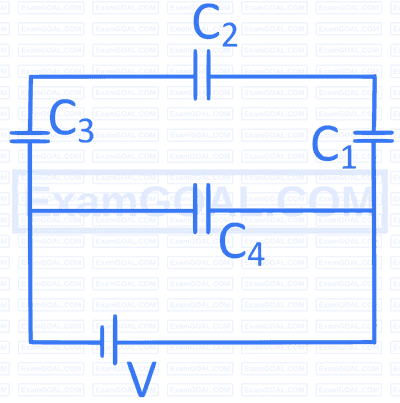
$C_1=3 \mu F, C_2=6 \mu F, C_3=3 \mu F$ and $C_4=4 \mu F$
Figure below shows a network of resistors, cells, and a capacitor at steady state.

What is the current through the resistance 4 $$\Omega$$ ?
A parallel plate capacitor having a dielectric constant 5 and dielectric strength $$10^6 \mathrm{~V} \mathrm{~m}^{-1}$$ is to be designed with voltage rating of $$2 \mathrm{~kV}$$. The field should never exceed $$10 \%$$ of its dielectric strength. To have the capacitance of $$60 \mathrm{~pF}$$ the minimum area of the plates should be
The figure shows a network of five capacitors connected to a 20 V battery. Calculate the charge acquired by each 10 $$\mu$$F capacitor.

A parallel plate capacitor is filled by a dielectric whose relative permittivity varies with the applied voltage (U) as $$\epsilon=2 U$$. A similar capacitor with no dielectric is charged to $$U_0=78 \mathrm{~V}$$. It is then connected to the uncharged capacitor with the dielectric. Find the final voltage on the capacitors.
A capacitor of capacity $$2 ~\mu \mathrm{F}$$ is charged upto a potential $$14 \mathrm{~V}$$ and then connected in parallel to an uncharged capacitor of capacity $$5 ~\mu \mathrm{F}$$. The final potential difference across each capacitor will be
A dielectric of dielectric constant $$K$$ is introduced such that half of its area of a capacitor of capacitance $$C$$ is occupied by it. The new capacity is
In the figure below, the capacitance of each capacitor is $$3 \mu \mathrm{F}$$. The effective capacitance between $$A$$ and $$B$$ is

If $$C$$ be the capacitance and $$V$$ be the electric potential, then the dimensional formula of $$\mathrm{CV}^2$$ is

In the figure, first the capacitors are fully charged by closing the key $$\mathrm{K}$$. Then after opening the Key a dielectric material with dielectric constant 2 is filled in the space between the plates of both the capacitor. At this state the ratio of the Charge on the capacitor $$C_1$$ to that of $$C_2$$ is:
If R and C denote resistance and capacitance of a material, then the dimension of CR will be :
In the network shown in figure, the equivalent capacitance between points P and Q is

Two capacitors $$C_1$$ and $$C_2$$ are charged to 120 V and 200 V, respectively. When they are connected in parallel, it is found that potential on each one of them is zero. Therefore,