Network Elements · Electric Circuits · GATE EE
Marks 1
$$ \text { The I-V characteristics of the elements between the nodes } X \text { and } Y \text { is best depicted } $$

A nullator is defined as a circuit element where the voltage across the device and the current through the device are both zero. A series combination of a nullator and a resistor of value, $R$, will behave as a
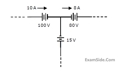
The number of junctions in the circuit is

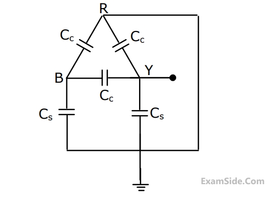
In the given circuit, for voltage Vy to be zero, the value of β should be ______. (Round off to 2 decimal places).

Currents through ammeters A2 and A3 in the figure are 1∠10° and 1∠70°, respectively. The reading of the ammeter A1 (rounded off to 3 decimal places) is _____ A.

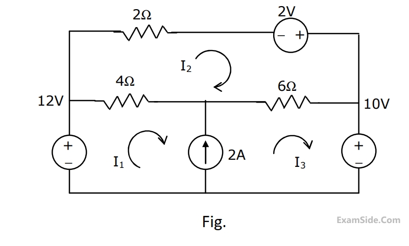
The current I flowing in the circuit shown below in amperes (round off to one decimal place) is ________.


Marks 2
In the circuit shown below, the magnitude of the voltage V1 in volts, across the 8 k$$\Omega$$ resistor is ________. (round off to nearest integer).


Marks 5