1
GATE ECE 2002
Subjective
+5
-0
The inputs to a digital circuit shown in Figure 9(a) are the external signals A, B and C.
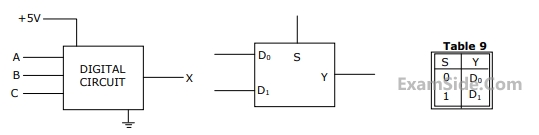 ( $$\overline A \,\overline B \,and\,\overline {C\,} $$ and are not available). The +5V power supply (logic 1) and the ground
(logic 0) are also available. The output of the circuit is X = $$\overline A \,B + \,\overline A \,\overline B \,\,\overline {C\,} $$
( $$\overline A \,\overline B \,and\,\overline {C\,} $$ and are not available). The +5V power supply (logic 1) and the ground
(logic 0) are also available. The output of the circuit is X = $$\overline A \,B + \,\overline A \,\overline B \,\,\overline {C\,} $$
(a) Write down the output function in its canonical SOP and POS forms.
(b) Implement the circuit using only two 2:1 multiplexers shown in the Figure where S is the data-select line, $${D_0}\,$$ and $${D_1}\,$$ are the input data lines and Y is the output lines. The function table for the multiplexer is given in table
Questions Asked from Combinational Circuits (Marks 5)
Number in Brackets after Paper Indicates No. of Questions
GATE ECE Subjects
Network Theory
Control Systems
Electronic Devices and VLSI
Analog Circuits
Digital Circuits
Microprocessors
Signals and Systems
Representation of Continuous Time Signal Fourier Series Discrete Time Signal Fourier Series Fourier Transform Discrete Time Signal Z Transform Continuous Time Linear Invariant System Transmission of Signal Through Continuous Time LTI Systems Discrete Time Linear Time Invariant Systems Sampling Continuous Time Signal Laplace Transform Discrete Fourier Transform and Fast Fourier Transform Transmission of Signal Through Discrete Time Lti Systems Miscellaneous Fourier Transform
Communications
Electromagnetics
General Aptitude